

The Art of Picking Mechanically Lined Pipe: What They Don’t Tell You in the Brochures
Look, I’ve been in this game for 22 years. Started as a shop floor inspector back in ’02, worked my way up through quality control, spent a decade in failure analysis, and now I’m the guy they call when a billion-dollar project is about to spec the wrong pipe. I’ve seen mechanically lined pipe save budgets, and I’ve watched it fail catastrophically because someone in a procurement office picked the cheapest option without understanding what they were actually buying.
Let me tell you something straight up. The difference between a mechanically lined pipe that lasts 30 years and one that starts delaminating after 18 months? It’s rarely about the raw materials. It’s about understanding what the hell you’re actually asking the pipe to do.
Why Mechanically Lined Pipe Even Exists
Back in the mid-90s, I was working on a North Sea project. We had this 16-inch flowline, solid duplex, cost an absolute fortune. The client was happy, we were happy, everyone went home with bonuses. Then the price of nickel went through the roof, and suddenly solid CRA pipe became economically insane for long-distance transport.
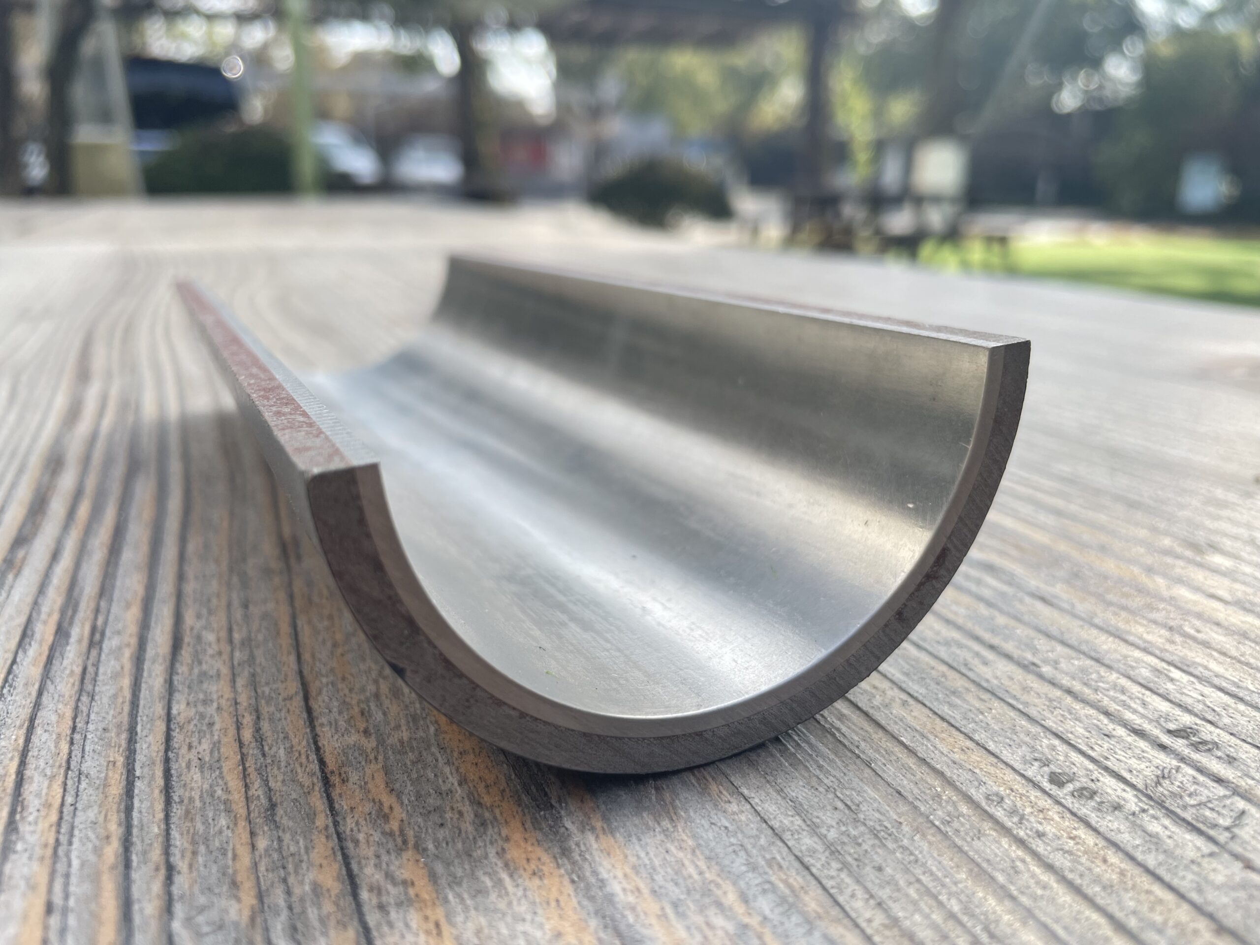
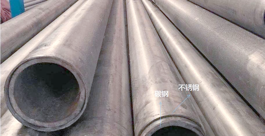
Here’s the thing. You don’t need the whole wall thickness to be corrosion resistant. You just need a barrier. The carbon steel gives you the strength and the pressure containment. The thin CRA liner—usually 2mm to 3mm—handles the nasty stuff. That’s the whole premise. But mechanically lined pipe isn’t cladded pipe, and if you don’t understand that distinction, you’re going to have a bad day.
Cladded pipe? That’s metallurgical bond. Fusion. You’re talking about roll bonding or explosion cladding where the liner and the backing steel become one continuous material at the interface. It’s beautiful when it’s done right, but it’s expensive and it takes forever to manufacture.
Mechanically lined pipe is different. We’re taking a CRA pipe, sliding it inside a carbon steel outer pipe, and then expanding the whole assembly so the liner presses against the outer pipe with enough residual contact pressure that it stays put. It’s a mechanical interference fit. No fusion. Just physics.
And here’s where most engineers get it wrong. They look at a spec sheet, see “lined pipe,” and assume it behaves like solid CRA. It doesn’t. Not even close.3
The Fundamental Question Nobody Asks
When a project manager comes to me and says “we need lined pipe for a sour service application,” my first question is always the same.
What temperature?
Not the design temperature from the process flow diagram. The actual operating temperature. The transient temperatures. The shutdown temperatures. The cooldown rates.
Because mechanically lined pipe lives and dies by differential thermal expansion.
Here’s the math that keeps me up at night. Carbon steel has a thermal expansion coefficient around 11.7 × 10⁻⁶ /°C. Your typical 316L liner? That’s about 16.0 × 10⁻⁶ /°C. So when you heat the pipe up, the liner wants to expand more than the outer pipe. That increases your contact pressure. Good thing, right?
But when you cool it down—say during a shutdown in a North Sea winter or a Canadian oil sands operation—the liner shrinks more. If you drop the temperature far enough, that interference fit goes away. Now you’ve got a loose liner. And a loose liner is a dead liner.
I had a job in Kazakhstan back in ’08. Beautiful design, everything spec’d perfectly on paper. But nobody thought about the -40°C winter shutdowns followed by rapid injection of 80°C produced fluids. First thermal cycle, the liner buckled. Wrinkled like an elephant’s knee. Had to cut out 3 kilometers of pipe and start over.
The lesson? You need to calculate your minimum contact pressure at every expected temperature. Not just steady-state. Every transient condition.
Let me give you the rough calculation we use for initial screening. The residual contact pressure at temperature T is:
P_c(T) = P_0 + [ (α_liner – α_cs) × (T – T_install) × E_liner × t_liner ] / D
Where:
-
P_0 is your initial contact pressure after manufacturing
-
α are the thermal expansion coefficients
-
E_liner is the modulus of the liner material
-
t_liner is the liner thickness
-
D is the nominal diameter
If that number goes negative at any point in your operating envelope, you’ve got problems. Full stop. Don’t pass go, don’t collect $200.
The Manufacturing Variable That Changes Everything
Here’s something you won’t see in the sales brochures. How do they actually expand the pipe?
There are basically two schools of thought in the industry. Hydraulic expansion and mechanical expansion. I’ve worked with both. I’ve fixed failures from both. And I have strong opinions.
Hydraulic expansion is what we use at our facility. You seal the ends of the lined assembly, fill the annulus with water (or sometimes oil), and pressurize the hell out of it. We’re talking 400 to 900 bar depending on the size and wall thickness. The pipe expands plastically, and when you release the pressure, the carbon steel springs back more than the liner, leaving that residual contact pressure I mentioned earlier.
The advantage? Uniform expansion. The whole length of the pipe sees the same pressure at the same time. Your contact pressure distribution is incredibly consistent.
The disadvantage? End effects. The last 100mm or so at each end of the pipe doesn’t expand quite the same because of the sealing arrangements. You either cut those ends off or you account for them in your design.
Mechanical expansion uses a pig or a mandrel that’s pulled or pushed through the assembly, mechanically stretching the pipe as it goes. Some of our competitors swear by it. Faster cycle times, less equipment, no water handling.
But here’s what I’ve seen in failure analysis. Mechanical expansion can leave circumferential variations. The pipe expands, relaxes, and sometimes you get these subtle ripples—microscopic variations in contact pressure around the circumference. Under normal operation, fine. But if you’re cycling temperature or pressure, those variations become initiation points for fatigue or fretting.
I’m not saying mechanical expansion is wrong. Some of my best friends make mechanically expanded pipe. But for critical service—deepwater, high temperature, severe sour—I spec hydraulic every time.
The Table Nobody Shows You
I keep a spreadsheet on my laptop. Updated it last week after reviewing some failure data from the Middle East. Here’s the simplified version of how I think about liner material selection.
| Service Condition | Liner Material | Minimum Thickness | Max Temp | Relative Cost | The Catch |
|---|---|---|---|---|---|
| Mild sour, sweet service, water injection | 316L | 2.5mm | 250°C | 1.0 | Chlorides will kill it above 60°C |
| Moderate sour, some chlorides | 904L | 2.5mm | 300°C | 1.8 | Welding is fussy, needs careful procedure |
| High H₂S, high chlorides, moderate temp | 825 | 2.5mm | 350°C | 2.4 | Availability is getting worse every year |
| Extreme sour, high temp, elemental sulfur | 625 | 3.0mm | 400°C | 3.2 | Hydrogen embrittlement concerns in liner |
| Tight spaces, weight sensitive | 2205 | 2.0mm | 200°C | 1.5 | Less ductile during expansion |
| Seawater injection, low temp | 316L | 3.0mm | 80°C | 1.0 | MIC can be an issue, consider Cu addition |
That “catch” column? That’s the stuff you only learn from watching pipes fail. Let me unpack a couple.
The 316L Chloride Trap
Everybody loves 316L. It’s cheap, it’s available, every fabricator knows how to weld it. But I’ve lost count of the number of failures I’ve seen where someone put 316L-lined pipe into a hot chloride service because “the temperature is only 80°C.”
Here’s the problem. That 80°C is bulk fluid temperature. But right at the pipe wall, especially if you’ve got any fouling or deposits, the surface temperature can be higher. And if you ever do a steam-out for cleaning? You’re suddenly at 130°C or more. Chloride stress corrosion cracking doesn’t care about your design basis. It cares about what actually happens.
I had a case in a东南亚 refinery—sorry, can’t name the client—where they used 316L-lined pipe for a produced water service. Design said 75°C max. But there was this one section downstream of a let-down valve where flashing caused localized heating. Nothing major, maybe 95°C at the wall. Six months later, we were pulling hairline cracks out of every second joint. The whole batch had to be scrapped.
If you’ve got chlorides and you’re above 60°C, I’m going to push you toward 904L or 825. Yes, it costs more. But it costs less than replacing 5 kilometers of pipe.
What the Standards Don’t Tell You About Hydrogen
There’s been a lot of talk in the industry lately about hydrogen transport. Repurposing existing gas pipelines for hydrogen, building new hydrogen infrastructure. And everyone’s asking about lined pipe for hydrogen service.
Here’s the thing that keeps me awake. Hydrogen embrittlement in CRA materials is complex, and the standards haven’t caught up yet. We have NACE MR0175/ISO 15156 for sour service, but hydrogen service is different. Higher pressures, different damage mechanisms.
I’m involved with a joint industry project right now—can’t say which one—looking at lined pipe for pure hydrogen at 100 bar plus. Early indications are that some of our assumptions about liner materials are wrong. Specifically, nickel alloys that we thought were immune? Not so much. There’s a hydrogen effects on the bond interface that we didn’t predict.
If you’re specifying lined pipe for hydrogen, and someone tells you confidently that “all the standards say it’s fine,” be suspicious. We’re still learning. Ask for test data. Ask for references. And build in a safety margin.
The Weld End Preparation Nightmare
Here’s something that causes more field problems than almost anything else. How do you terminate the lined pipe?
You’ve got this beautiful pipe, perfect interference fit, lovely smooth bore. Then you need to weld it to the next joint or to a fitting. And suddenly you’ve got to deal with the liner at the weld end.
There are basically four approaches, and I’ve seen all of them fail when done wrong.
Method 1: Exposed liner. You cut both pipes back, leaving the liner protruding. Then you weld the carbon steel outer pipes together, and then you weld a closure piece between the liners. This gives you a continuous CRA surface. It’s beautiful when it’s done right. But it’s slow, it requires highly skilled welders, and you’ve got to manage fit-up perfectly. I’ve seen more than a few field failures where the closure weld cracked because somebody got the gap wrong.
Method 2: Overlay welding. You weld the carbon steel joint first, then you go inside and weld overlay the exposed carbon steel with CRA filler metal. This is faster, more forgiving of fit-up issues. But now you’ve got a transition from the original liner to the weld overlay. If that transition isn’t smooth, you’ve got a crevice. And crevices are where corrosion starts.
Method 3: Clad weld ends. Some manufacturers supply pipe with an integral clad transition at the ends. The last 50mm or so of the pipe is actually metallurgically cladded rather than mechanically lined. You weld the carbon steel, and the clad end protects the weld area. This is my preferred approach for critical service. It costs more upfront, but it saves a fortune in field welding time.
Method 4: Internal sleeves. You weld the carbon steel, then you insert a separate CRA sleeve that spans the joint and seal weld it at both ends. This is common in retrofit situations. But now you’ve got two circumferential seal welds per joint, and each one is a potential leak path.
I had a project in the North Sea where the contractor decided to save money by using exposed liners with unskilled welders. First pressure test, we had leaks at 30% of the joints. The rework cost three times what proper overlay welding would have cost upfront.
The Inspection Trap
Here’s another one. How do you inspect mechanically lined pipe after installation?
You can’t just run a standard intelligent pig. Most inspection tools are designed for solid wall pipe. They measure wall thickness or look for metal loss. But in lined pipe, you’ve got two layers, and the bond between them isn’t magnetic or ultrasonic in a simple way.
I worked with a pipeline operator a few years back who ran a standard magnetic flux leakage tool through their lined pipe. The tool reported “wall loss” at multiple locations. They dug up the pipe, cut out sections, and found nothing. The tool was seeing the interface between the liner and the outer pipe as a defect.
What you actually need is specialized ultrasonic tools that can discriminate between the layers. And even then, you’re mostly looking for liner disbondment or buckling, not traditional corrosion. The inspection world hasn’t fully caught up with lined pipe technology.
If you’re putting lined pipe in a critical location where you’ll need ongoing integrity monitoring, think about this upfront. Can you run the inspection tools you’ll need? Is the pipeline designed for the tool access? Or are you going to be guessing about liner condition in 10 years?
The Personal Story That Changed My Mind
Let me tell you about a job in West Africa. Deepwater project, big name operator, all the engineering resources you could imagine. They’d specified 825-lined pipe for a flowline carrying hot, sour production. Everything looked right on paper.
But when the first batch of pipe arrived, our inspection team noticed something odd. The liner surface had a slight discoloration pattern. Almost like watermarks. The manufacturer said it was just handling marks, no big deal.
I flew out to look at it myself. Took a portable hardness tester to the liner in about 50 locations. The hardness was consistent, which was good. But I still didn’t like those marks.
We ended up cutting a sample from one of the “suspect” pipes and sending it for metallography. What we found was surprising. During the hydraulic expansion process, there had been some contamination in the pressurizing fluid. Microscopic particles had embedded in the liner surface. Nothing that affected corrosion performance in the short term. But in a high-chloride, high-temperature environment? Those embedded particles could become initiation sites for pitting.
We rejected the whole batch. The manufacturer was furious. The project schedule took a hit. But three years later, when that field came online and started producing, I got a call from the operator’s integrity manager. They’d had some corrosion issues in other parts of the facility, but the lined pipe? Perfect. Not a single pit.
That experience taught me something. The difference between good lined pipe and great lined pipe isn’t always in the specification. It’s in the process control. It’s in the cleanliness. It’s in the attention to detail during manufacturing.
The Cost Question Nobody Answers Honestly
People ask me all the time: “How much cheaper is mechanically lined pipe than solid CRA?”
The honest answer is: it depends, and anyone who gives you a single number is lying.
For a standard 12-inch schedule 40 pipe in 316L, lined pipe might be 40% cheaper than solid 316L. But for a heavy wall 20-inch pipe in 625, the savings can be 70% or more. The thicker the carbon steel backing, the more you save, because you’re replacing expensive alloy with cheap carbon steel.
But here’s the trap. Installation costs are different. Welding lined pipe takes longer. Inspection is more complicated. Fittings and flanges need special attention. So your installed cost ratio might be different from your material cost ratio.
I always tell clients to do a total installed cost comparison, not just a material cost comparison. And factor in the cost of potential failure. For a low-risk, low-temperature water injection line, lined pipe is a no-brainer. For a high-temperature, high-pressure sour gas line with limited access for repair, maybe solid CRA starts looking attractive again.
The Future and Why I’m Worried
I’m going to be honest with you. The lined pipe industry is facing some challenges right now.
First, raw material availability. The nickel alloy market has been volatile for years. Lead times for 825 and 625 are stretching out. Some projects are waiting 12 months or more for liner materials. That’s pushing people toward less suitable alternatives or toward suppliers with questionable quality.
Second, skill shortage. The people who really understand lined pipe—the metallurgy, the manufacturing, the failure modes—are retiring. I’m 58, and I’m one of the younger guys in the failure analysis community. The institutional knowledge is walking out the door, and I’m not sure the next generation is ready to catch it.
Third, the hydrogen question. If hydrogen transport takes off the way everyone predicts, we’re going to need enormous quantities of lined pipe. But we don’t fully understand the long-term performance yet. There are research programs happening, but they take time. I’m worried that the commercial pressure will outrun the technical understanding.
And fourth, the quality squeeze. There are manufacturers out there cutting corners. Using lower grade liner materials, reducing expansion pressures, skipping quality checks. They get away with it because the pipe passes initial inspection. But 5 years down the road, someone’s going to have a very expensive problem.
My Rules of Thumb
After 22 years, I’ve boiled this down to a few simple rules. They won’t replace proper engineering, but they’ll keep you out of trouble while you’re doing the proper engineering.
Rule 1: If you can’t calculate the minimum contact pressure at every expected condition, you haven’t finished the design.
Rule 2: The liner thickness is your corrosion allowance. If you spec 2.5mm, that’s what you get. Don’t assume you have margin.
Rule 3: Weld ends are the weak point. Spend money there.
Rule 4: If the price is too good to be true, someone’s skipping something.
Rule 5: Talk to the people who made the pipe, not just the sales rep. Ask about their process control. Ask about their rejection rates. Ask about their last failure investigation.
Rule 6: For critical service, cut and test at least one production joint before you accept the whole batch. It’s cheap insurance.
A Recent Example That Keeps Me Humble
Last year, I consulted on a project in the Middle East. Giant gas field, high CO₂, moderate H₂S, temperatures around 120°C. The client had specified 825-lined pipe, 3mm liner, all looked good.
But during the detailed design review, I noticed something. The pipeline had several sections that would be installed using reeling. The pipe would be spooled onto a large drum, transported, then straightened during installation.
Nobody had checked what that bending does to the liner contact pressure.
We ran some quick FEA. During reeling, the compressive strains on the inside of the bend were high enough to cause local liner buckling in the as-manufactured condition. Not during operation—during installation.
We ended up requalifying the pipe with a thicker liner and a modified expansion process to increase initial contact pressure. It added cost and schedule. But if we hadn’t caught it, that pipe would have had loose liners before it even reached the seabed.
The point is, lined pipe isn’t just a material selection. It’s a system. You have to think about every phase of its life: manufacturing, transportation, installation, operation, inspection. Each phase imposes different loads on that mechanical bond.
The Bottom Line
Mechanically lined pipe is a brilliant solution when it’s applied correctly. It’s saved the industry billions of dollars compared to solid CRA. It’s enabled projects that would have been economically impossible otherwise.
But it’s not magic. It’s not a substitute for understanding what you’re doing. The bond between the liner and the outer pipe is mechanical, not metallurgical. It has limits. It has failure modes. It demands respect.
Technical Analysis Diagrams for Mechanically Lined Pipe Selection
Anchor Cage Misalignment: Before vs After Pour
This is what keeps happening when you don’t use a top template. The cage shifts during concrete placement.
PLAN VIEW - TOP OF FOUNDATION
(LOOKING DOWN)

DESIRED POSITION                    ACTUAL POSITION
(Spec: ±1/8" tolerance)             (What we found in SC: 1.5" shift)

      N                                    N
      |                                    |
      |                                    |
W-----+-----E                         W-----+-----E
      |                                    |    X
      |                                    |   X
      S                                    S   X
                                           XXX
                                      Cage shifted SE

ANCHOR BOLT CIRCLE
(12 bolt pattern shown simplified)

Desired:  ○ ○ ○ ○ ○ ○ ○ ○ ○ ○ ○ ○
Found:    ○ ○ ○ ○ ○ ○ ○ ○ ○ X X X X
                                  (3 bolts out of position)
The math on this? Eccentricity e = 1.5 inches. On a 120-ft monopole, that eccentricity creates an additional moment:
Where P is the vertical load. For a 50-kip tower weight, that’s an extra 6,250 ft-lbs of bending at the base that nobody designed for. The tower never stands straight. It’s born leaning.
Plumbness Measurement: The 3-Face Check
Most crews check from two sides. On a triangular tower, that’s not enough. Here’s why:
SECTION A-A THROUGH TOWER
(LOOKING DOWN FROM ABOVE)

     Face A
       /\
      /  \
     /    \
    /      \
   /        \
  /          \
 /            \
/              \
\              /
 \            /
  \          /
   \        /
    \      /
     \    /
      \  /
       \/
     Face C    Face B

MEASUREMENT POINTS:
Theodolite positions at 120° intervals:
Position 1: Sight along Face A
Position 2: Rotate 120°, sight along Face B
Position 3: Rotate 120°, sight along Face C

DEFLECTION READINGS (inches at top):

Tower "A" (Looks straight from two sides):
Face A: +1.0" (leans north)
Face B: +0.5" (leans NE)
Face C: -1.5" (leans SW)  ← Problem!
Average deflection = (1.0 + 0.5 - 1.5)/3 = 0.0
But max deviation = 1.5" → Twist present

Tower "B" (Actually straight):
Face A: +0.2"
Face B: +0.1"
Face C: -0.3"
Average = 0.0, max = 0.3" ✓
The twist in Tower A puts torsion into every connection. Bolts on Face C are taking more shear than designed. That’s a fatigue failure waiting to happen.
Turn-of-Nut Method: Bolt Tension Progression
This is what happens inside a bolt when you tighten it properly:
BOLT TENSION vs. NUT ROTATION
(For A325 bolt, 3/4" diameter x 4" long)

Tension
  ^
  |                              X <-- Final: 1/3 turn
  |                            X      (~28,000 lbs)
  |                          X
  |                        X
  |                      X
  |                    X
  |                  X
  |                X
  |              X
  |            X
  |          X
  |        X
  |      X
  |    X
  |  X
  |X <-- Snug tight (~1,000 lbs)
  +------------------------------------> Rotation
  0  1/8  1/4  3/8  1/2  5/8  3/4 (turns)

WHAT THE WRENCH FEELS LIKE:

Snug tight:   "Contact... a little more..."
1/8 turn:     "Getting firm..."
1/4 turn:     "This is taking effort..."
1/3 turn:     "GRUNT. OK, that's done."

DANGER ZONE (Over-torqued):
1/2 turn:     "Why is it getting easier? Oh sh--"
              (Bolt yields, permanent stretch, reduced clamping force)
The torque wrench lies. Temperature, lubrication, thread condition—all affect torque. But stretch is stretch. The turn-of-nut method doesn’t care about friction.
Cable Thermal Movement: Why You Need Service Loops
Temperature change makes cables expand and contract. This is what happens when you don’t allow for it:
VERTICAL CABLE RUN - 100 FT HEIGHT
(Winter vs Summer position)

Top Connector                         Top Connector
      |                                     |
      |                                     |
      | Winter (-20°F)                      | Summer (+100°F)
      | Cable shortened                      | Cable lengthened
      |                                      |
      |                                      |
      |                                      |
      |                                  ___/    Service
      |                                 /        loop
      |                                /         takes up
      |                               /          slack
      |                              /
      |                             /
      |                            /
      |                           /
      |                          /
      |                         /
      |                        /
      |                       /
      |                      /
      |                     /
      |                    /
      |                   /
      |                  /
      |                 /
      |                /
      |               /
      |              /
      |             /
      |            /
      |           /
      |          /
      |         /
      |        /
      |       /
      |      /
      |     /
      |    /
      |   /
      |  /
      | /
      |/
Bottom Connector                     Bottom Connector

CABLE LENGTH CHANGE:
ΔL = L × α × ΔT

For L = 100 ft = 1200 inches
α (copper) ≈ 9.4 × 10⁻⁶ /°F
ΔT = 120°F (from -20°F to +100°F)

ΔL = 1200 × 9.4e-6 × 120 = 1.35 inches

Without service loop: That 1.35 inches pulls the connector.
With service loop: Loop opens/closes, connector stays put.
The Arizona site I mentioned? They had no loops. Winter night, -20°F cold snap (rare, but happened). Cables shrank 1.5 inches. Popped three connectors right off the jacks. Radio silence at 3 AM. The client wasn’t happy.


You must be logged in to post a comment.