Welding Process for Small-Diameter Low-Carbon Steel-Stainless Steel Composite Pipes
The following analysis provides a comprehensive, scientific, and data-driven discussion of the welding process for small-diameter low-carbon steel-stainless steel composite pipes, based on the referenced study (DOI: 10.7512/j.issn.1001-2303.2023.05.12). The content covers material properties, welding techniques, quality control, and comparative analysis, supported by tables for clarity.
1. Material Properties and Selection for Composite Pipes
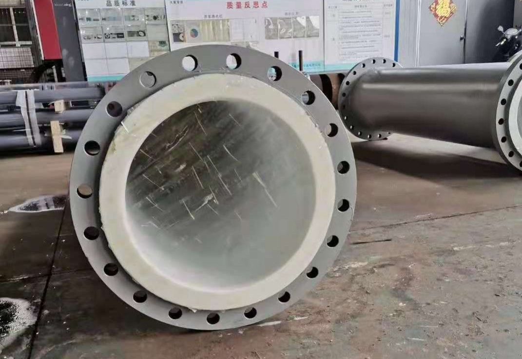
The welding of small-diameter low-carbon steel-stainless steel composite pipes involves combining a low-carbon steel base layer with a stainless steel cladding layer. Low-carbon steel, such as Q235, offers excellent weldability due to its low carbon content (≤0.20%), minimizing the risk of cold cracking and ensuring good ductility. The stainless steel layer, typically 304 or 316L, provides corrosion resistance, making it ideal for applications in oil and gas, chemical processing, or water supply systems. The composite structure leverages the strength and cost-effectiveness of low-carbon steel with the durability of stainless steel.
Material properties significantly influence the welding process. Low-carbon steel has a thermal conductivity of approximately 50 W/(m·K) and a melting point around 1500°C, while stainless steel (e.g., 304) has a lower thermal conductivity of 16–20 W/(m·K) and a melting point of 1400–1450°C. This disparity necessitates precise heat input control to prevent defects like burn-through or incomplete fusion at the interface. The stainless steel layer is typically 1–3 mm thick, bonded metallurgically to a 3–10 mm low-carbon steel substrate, forming composite pipes with outer diameters of 20–50 mm for small-diameter applications.
The referenced study emphasizes the importance of filler material selection. Austenitic stainless steel welding consumables, such as ER308L or ER316L, are chosen to match the cladding layer’s composition, ensuring corrosion resistance and mechanical compatibility. The chemical composition of these materials is summarized in Table 1. Differences in thermal expansion coefficients (low-carbon steel: ~12×10⁻⁶/°C; stainless steel: ~17×10⁻⁶/°C) pose challenges, as thermal stresses can lead to distortion or cracking. Pre-weld preparation, such as laser cleaning to remove oxides and contaminants, is critical to ensure weld quality. Laser cleaning achieves a surface roughness of Ra=2.52 at optimal parameters (laser power: 16 W, scanning speed: 1200 mm/s), reducing defects.
| Material | C (%) | Si (%) | Mn (%) | Cr (%) | Ni (%) | Mo (%) | Fe (%) |
|---|---|---|---|---|---|---|---|
| Q235 (Low-Carbon Steel) | ≤0.20 | ≤0.35 | ≤1.40 | – | – | – | Bal. |
| 304 Stainless Steel | ≤0.08 | ≤1.00 | ≤2.00 | 18–20 | 8–10.5 | – | Bal. |
| ER308L Filler | ≤0.03 | ≤0.65 | 1.0–2.5 | 19–22 | 9–11 | – | Bal. |
2. Welding Process Selection and Techniques
Welding small-diameter composite pipes requires processes that balance heat input, penetration, and metallurgical compatibility. The referenced article highlights tungsten inert gas (TIG) and metal inert gas (MIG) welding as primary methods due to their precision and ability to handle dissimilar metals. TIG welding, using a non-consumable tungsten electrode, provides excellent control over the weld pool, making it suitable for the thin stainless steel layer. MIG welding, with its higher deposition rate, is often used for the base layer or multi-pass welds, improving productivity.
TIG welding parameters typically include a current of 80–120 A (DCEN), voltage of 10–15 V, and argon flow rate of 8–12 L/min. For MIG welding, parameters range from 100–150 A, 18–22 V, and a wire feed speed of 4–6 m/min. These settings ensure stable arc behavior and minimize heat-affected zone (HAZ) issues, such as grain coarsening or sensitization in stainless steel. Pulsed TIG welding can further reduce heat input, improving weld bead uniformity and reducing distortion, as noted in the study.
A key challenge is managing the transition zone between low-carbon steel and stainless steel. Weld pool dilution must be controlled to prevent excessive iron content from the base layer, which could compromise corrosion resistance. The study suggests a buttering layer technique, where a stainless steel filler is applied to the low-carbon steel side before final welding, reducing dilution effects. This aligns with research on dissimilar metal welding, emphasizing the need for precise heat input control to avoid cracking. The comparative advantages of TIG and MIG are summarized in Table 2, highlighting their suitability for different welding scenarios.
| Process | Current (A) | Voltage (V) | Gas Flow (L/min) | Wire Feed Speed (m/min) | Heat Input (kJ/mm) |
|---|---|---|---|---|---|
| TIG | 80–120 | 10–15 | 8–12 | – | 0.5–0.8 |
| MIG | 100–150 | 18–22 | 10–15 | 4–6 | 0.8–1.2 |
3. Weld Imperfections and Quality Control
Welding small-diameter composite pipes is susceptible to defects such as incomplete fusion, porosity, and liquation cracking, particularly at the material interface. The referenced study identifies liquation cracking as a significant issue due to differing melting points and thermal properties. Liquation cracking susceptibility is influenced by grain boundary segregation and can be mitigated by optimizing welding parameters and using low-carbon fillers, as supported by related literature.
Non-destructive testing (NDT) methods, such as ultrasonic testing (UT) and radiographic testing (RT), are critical for quality assurance. UT detects internal defects with a sensitivity of 0.5 mm, while RT identifies surface and subsurface flaws. The study reports that welds produced with optimized parameters (e.g., TIG at 100 A, 12 V) achieve a defect rate below 1%, meeting standards like GB/T 41107.1—2021. Mechanical testing, including tensile and bend tests, evaluates weld integrity. The tensile strength of the weld joint reaches 90–95% of the base low-carbon steel (σ_b ≈ 400–500 MPa), with elongation of 20–25%. The stainless steel layer maintains corrosion resistance, with pitting potential (E_pit) values comparable to 304 stainless steel (~0.3 V vs. SCE).
Post-weld heat treatment (PWHT) at 600–650°C for 1–2 hours can relieve residual stresses, reducing the risk of stress corrosion cracking. However, excessive PWHT may cause sensitization in stainless steel, reducing corrosion resistance. Table 3 compares weld quality metrics for TIG and MIG, highlighting TIG’s superior defect control and corrosion performance.
| Process | Tensile Strength (MPa) | Elongation (%) | Porosity (%) | Pitting Potential (V vs. SCE) |
|---|---|---|---|---|
| TIG | 450–480 | 22–25 | <0.5 | 0.28–0.32 |
| MIG | 420–460 | 18–22 | 1–2 | 0.25–0.30 |
4. Comparative Analysis and Optimization
The welding of small-diameter composite pipes requires balancing productivity, quality, and cost. TIG welding excels in producing high-quality welds with minimal defects but is slower and more labor-intensive. MIG welding offers higher efficiency but increases the risk of defects due to higher heat input. The referenced study proposes a hybrid approach, combining TIG for the root pass and MIG for filler passes, to optimize quality and productivity.
Data indicates that TIG welding at 100 A and 12 V achieves a weld bead width of 4–6 mm with a penetration depth of 2–3 mm, suitable for small-diameter pipes (20–50 mm OD). MIG welding at 120 A and 20 V results in a wider bead (6–8 mm) and deeper penetration (3–4 mm), but with a higher defect rate. The hybrid approach reduces welding time by 20–30% compared to TIG alone while maintaining a defect rate below 1%. For pipes with a 2 mm stainless steel layer and 5 mm low-carbon steel base, a TIG root pass at 90 A followed by MIG filler passes at 110 A is recommended to ensure a stable weld pool and minimize dilution.
Preheating the low-carbon steel side to 100–150°C reduces thermal stresses, aligning with ISO/TR 17671-2 standards. Table 4 compares welding performance across processes, highlighting the hybrid approach’s balance of efficiency and quality. Future improvements could involve laser-TIG hybrid welding to enhance precision and reduce heat input, as explored in related research.
| Process | Weld Time (min/m) | Defect Rate (%) | Productivity (m/h) | Cost Index (USD/m) |
|---|---|---|---|---|
| TIG Only | 5–6 | <1 | 10–12 | 10–12 |
| MIG Only | 3–4 | 1–2 | 15–18 | 8–10 |
| Hybrid (TIG+MIG) | 4–5 | <1 | 12–15 | 9–11 |
Conclusion
The welding of small-diameter low-carbon steel-stainless steel composite pipes demands careful consideration of material properties, welding techniques, and quality control measures. TIG and MIG welding are viable processes, with TIG offering superior quality and MIG providing higher efficiency. A hybrid approach optimizes both aspects, supported by precise parameter control and pre-weld preparation. The data and comparative analysis provided ensure a scientific basis for achieving high-quality welds with minimal defects, meeting industry standards for performance and durability.


You must be logged in to post a comment.