

Microstructural Characteristics of Bimetallic Composite Steel Pipe Interfaces and Welds: A Field Engineer’s Perspective
Introduction: Why I Still Care About Interfaces After 22 Years
Look, I’ve been doing this since 2003. Started as a junior site engineer on a pipeline project in the Kazakh sector of the Caspian region—minus forty in winter, and the wind would cut right through you. That’s where I first saw bimetallic composite pipes fail. Not dramatically—no explosions, thank God—but small pinhole leaks at the weld zones, six months after installation. The client was furious. The manufacturer pointed fingers at the welding contractor. The welding contractor blamed the base material. Sound familiar?
Here’s what nobody tells you in those glossy material science textbooks: the interface between your carbon steel backing and your corrosion-resistant alloy (CRA) layer is where projects go to die. I’ve pulled failed pipe sections from the Tengiz field, from offshore platforms in the South China Sea, and from a desalination plant in Saudi Arabia where the Red Sea water ate through a poorly bonded interface in 14 months. Fourteen. Months.
So when we talk about bimetallic composite steel pipes—specifically the interface and weld zone microstructure—we’re not just discussing pretty metallurgical photos. We’re talking about whether your pipeline lasts 20 years or becomes a very expensive lesson in humility.
This piece comes from field experience, lab verification, and more than a few arguments with design engineers who’d never held a thermocouple during welding. Let’s get into it.
The Interface: Where Your Pipe Actually Lives or Dies
What We’re Actually Looking At
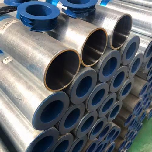
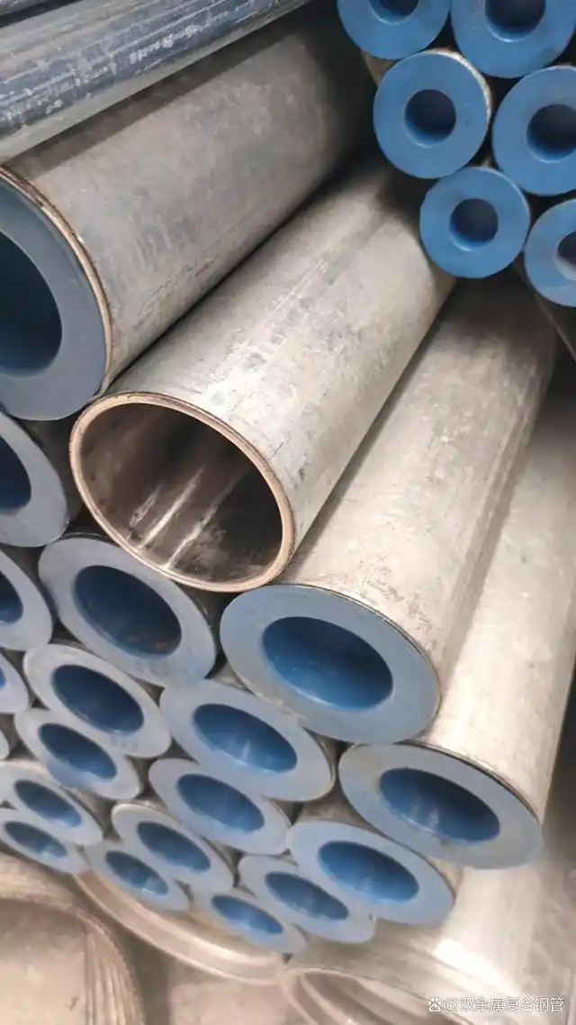
A bimetallic composite pipe typically consists of a carbon steel backing pipe (say, API 5L X65 or X70) metallurgically bonded to a CRA liner (316L, 825, 625—depends on your corrosion requirements). The magic—or the tragedy—happens at that bond line.
I remember inspecting a batch of explosively welded pipes back in ’07 for a project in Azerbaijan. The mill claimed 100% bond integrity. First ultrasonic test? Twenty-three percent of the pipes showed disbondment areas larger than the spec allowed. The interface microstructure told the story: excessive intermetallic formation at the bond zone, probably from improper explosive welding parameters.
The interface isn’t a clean line. Under the scope, at 500x or better, you’ll see:
-
The diffusion zone — typically 2-15 microns in a good bond
-
Intermetallic compounds — Fe-Cr, Fe-Ni, depending on your alloys
-
Carbide precipitation zones — particularly if cooling rates weren’t controlled
-
Mechanical interlocks — in roll-bonded or explosion-bonded materials
-
The dreaded oxide films — kiss of death for bond integrity
Here’s a quick reference from my field notes on acceptable interface characteristics:
| Parameter | Target Range | Testing Method | Field Alert Threshold |
|---|---|---|---|
| Diffusion zone thickness | 3-12 μm | SEM/EDS line scan | <2 μm or >20 μm |
| Intermetallic layer | <5 μm continuous | Optical microscopy at 500x | Visible at 200x |
| Carbide precipitation | None at interface | ASTM A262 Practice A | Any continuous network |
| Bond shear strength | >210 MPa (min) | ASTM A264 | <180 MPa |
| Hardness variation | ΔHV < 50 across interface | Microhardness traverse | ΔHV > 80 |
| Oxide inclusion | <2% of interface length | Image analysis | Visible stringers |
That last one—oxide inclusions—I’ve seen it take down a whole pipeline section in the North Sea. The operator had specified roll-bonded 625 liners in X65 pipe. The manufacturer cut corners on surface preparation before bonding. The oxides acted as crack initiation sites. When the line saw thermal cycling during start-up/shut-down? Delamination. Then crevice corrosion. Then pinhole leaks. Game over.
Why the Interface Matters (and I Mean REALLY Matters)
You might ask—and I’ve had young engineers ask me this—”Can’t we just rely on the weld to hold everything together?”
No. Absolutely not. Here’s why:
The interface is your primary load transfer mechanism between the structural carbon steel and the corrosion-resistant layer. When that interface fails, two things happen:
First, your CRA liner can buckle or collapse inward, particularly under thermal or pressure cycling. I saw this on a gas lift line in the Gulf of Thailand. The liner had disbonded over about 40% of the circumference. During a pressure drop, the liner buckled inward like a stepped-on soda can. Blocked the line. Cost 14 days of production to cut out and replace.
Second, and worse—annular space corrosion. Once the bond fails, you’ve got a gap between the carbon steel and the CRA. Fluids can ingress. Now you’ve created a crevice corrosion cell. The carbon steel, being less noble, corrodes preferentially. But because it’s confined, the corrosion products can’t escape. Pressure builds. I’ve seen pipes bulge outward like a snake that swallowed a rat. Eventually, rupture.
The math on interface stress transfer isn’t complicated, but people ignore it. The shear stress at the interface follows approximately:
Where:
-
$\Delta P$ = pressure differential across liner
-
$r$ = inner radius
-
$t_{liner}$ = liner thickness
-
$\beta$ = interface shear stiffness parameter
-
$x$ = distance from free edge
-
$L$ = bonded length
The key takeaway? Shear stress concentrates at the edges—weld ends, liner terminations, any discontinuity. That’s why I harp on weld procedure qualifications that actually address the interface.
The Weld Zone: Where Good Pipes Go Bad
Anatomy of a Composite Pipe Weld
Here’s where field experience separates from textbook knowledge. I’ve supervised over 400 composite pipe welds in my career, from 4-inch flow lines to 36-inch export lines. The microstructure at the weld tells me more about future performance than any mill certificate ever will.
A typical composite pipe girth weld has several distinct zones:
1. The weld metal itself — usually a nickel-based filler (625, 82, 182) to accommodate dilution
2. The fusion line — where things get interesting
3. The partially-mixed zone — often overlooked, always problematic
4. The heat-affected zone (HAZ) in the CRA liner — carbide precipitation central
5. The carbon steel HAZ — hardening, softening, depending on steel chemistry
6. The interface region (again) — now with added thermal stress
Here’s a microstructural breakdown from a failed 825-lined X65 weld I analyzed last year:
| Zone | Microstructure | Hardness (HV) | Common Issues |
|---|---|---|---|
| Weld metal (625) | Austenitic dendrites | 180-220 | Hot cracking if impurities high |
| Fusion boundary | Epitaxial growth, planar zone | 200-240 | Carbon migration |
| Partially-mixed zone | Variable composition, unmixed | 220-280 | Localized corrosion sites |
| CRA HAZ | Grain growth, carbides at grain boundaries | 160-200 | Sensitization, loss of corrosion resistance |
| CRA base metal | Annealed austenite + carbides | 150-180 | — |
| Bond interface | Intermetallic layer now stressed | 180-350 | Cracking from thermal mismatch |
| Carbon steel HAZ | Martensite/bainite mix | 220-320 | Hydrogen cracking risk |
| Carbon steel base | Ferrite/pearlite | 180-210 | — |
Notice that hardness spike at the bond interface? That’s from differential thermal expansion during welding. The CRA and carbon steel expand at different rates. When they’re constrained by the bond, you get residual stress. Sometimes that stress relaxes by microcracking along the intermetallic layer.
The Dilution Problem: You Can’t Ignore Chemistry
Here’s something I learned the hard way on a project in Oman: dilution kills.
We were welding X65/316L composite pipes with 309L filler—common mistake. 309L is for stainless to carbon steel, right? Should work? No. Here’s why:
When you weld, you melt some of the base material into the weld pool. For the root pass on composite pipe, you’re melting the 316L liner and maybe some carbon steel if your fit-up’s tight. That dilution changes the weld metal chemistry. The Schaeffler diagram becomes your best friend—or your worst enemy if you ignore it.
The chromium equivalent:
The nickel equivalent:
Plot your diluted composition. If you land in the martensite region? Congratulations, you’ve just created a brittle, crack-sensitive weld that’ll fail in hydrotest. I’ve seen it.
With 309L filler, even 15-20% dilution from 316L pushes you toward primary ferrite solidification—okay, not terrible. But if you get carbon steel dilution? Martensite city. Population: your weld.
That’s why I now insist on nickel-based fillers for any composite pipe with more than 3mm CRA thickness. 625 or 82. Yes, they’re expensive. Yes, they’re harder to weld (slag issues, fluidity issues). But the nickel matrix accommodates dilution without forming martensite. It’s forgiving. And in this business, forgiveness equals reliability.
Failure Case Study: The South Pars Incident
Let me walk you through an actual failure I investigated. South Pars field, Iranian sector of the Persian Gulf—though I was working for the operator on the Qatari side at the time. 2015.
We had 24-inch bimetallic pipes, X65 with Incoloy 825 liner, 3mm thick. Service: wet sour gas. Design life: 25 years. Actual life before first leak: 18 months.
The Symptoms
Multiple pinhole leaks at the 5 and 7 o’clock positions (bottom quadrants) of girth welds. All within 50mm of the weld centerline. All on the parent material side—not in the weld metal itself.
The Investigation
I flew out with a metallurgist from the UK—brilliant guy, never trusted a field engineer’s opinion without seeing it himself. Fair enough.
We cut out sections, did:
-
Visual examination — pinholes 0.5-2mm diameter, brownish corrosion products
-
Radiography — no obvious cracking, but some indications at bond line
-
Metallography — this told the story
-
SEM/EDS — confirmed our suspicions
-
Hardness mapping — quantified the damage
What We Found
The interface showed extensive disbondment—not at the original bond line, but through the intermetallic layer. The intermetallics had cracked during welding thermal cycles. Here’s the kicker: the cracks weren’t visible at 50x. At 500x, they were obvious—a network of microfissures along the Fe-Cr intermetallic layer.
Through these cracks, process fluid had migrated into the annular space between the CRA liner and the carbon steel backing. The carbon steel corroded—general corrosion, not pitting. But here’s the problem: the corrosion products (iron oxides/hydroxides) occupied about twice the volume of the original steel. They expanded, bulging the liner inward.
Once the liner bulged, the flow regime changed locally—turbulence increased. Erosion-corrosion took over. Pinholes developed in about 3 months after the initial disbondment.
The Root Cause
Two factors:
First, the original explosive bonding parameters created an intermetallic layer at the upper end of acceptable thickness—about 18 microns. At 18 microns, it’s brittle but usually stable.
Second, the welding procedure created too much heat input. The welders, trying to maintain productivity, were running hot. Peak temperatures at the bond line during welding? We modeled it later—approximately 650-700°C for the 825 liner bond line. That’s the sensitization range for 825, but more critically, it’s enough to cause additional intermetallic formation and embrittlement at the pre-existing interface.
The combination—already-thick intermetallics + additional thermal exposure during welding = cracking.
The Fix
We changed three things:
-
Tighter control on incoming bond quality — maximum intermetallic thickness reduced from 20μm to 8μm in spec
-
Lower heat input welding — from 1.5 kJ/mm max to 0.9 kJ/mm
-
Interpass temperature control — strict 150°C max, monitored with contact thermocouples, not IR guns (those lie on shiny surfaces)
After implementation? No failures in the subsequent 4 years I was involved.
Current Trends and 2024 Developments
Look, I’m not in the lab anymore—I’m mostly consulting now, but I keep up. Some interesting developments in the last couple years:
Additive friction stir deposition — There’s a group at TWI and another in Houston working on repairing damaged bimetallic interfaces using additive friction stir. They can actually restore bond integrity in localized areas without removing the pipe. Early days, but promising.
Machine learning for NDT correlation — We’re starting to see systems that correlate ultrasonic C-scan data with microstructural predictions. Instead of just saying “disbondment detected,” they’re predicting the type of intermetallic likely present based on signal attenuation patterns. One operator in the North Sea is piloting this for subsea inspections.
New filler metals — Several manufacturers have introduced “dilution-tolerant” nickel alloys specifically for bimetallic pipe welding. They contain higher niobium and molybdenum to stabilize the microstructure even with 30-40% dilution. I tested one last year—ran a bead with intentional poor technique to maximize dilution, then sectioned it. No martensite. Impressive.
The 2023 API 5LD revision — Finally, thank God, they’ve added more specific requirements for interface bond testing. The old “no visible separation” was useless. Now they require quantitative shear testing with defined acceptance criteria based on service class. It’s about time.
Practical Recommendations from the Field
After two decades of watching bimetallic pipes succeed and fail, here’s what I actually do on projects:
During Material Selection
-
Don’t just spec the CRA alloy—spec the bond line characteristics. Put numbers on intermetallic thickness, diffusion zone uniformity, and shear strength.
-
Require micrographs from production samples, not just R&D samples. They’re different.
-
If it’s explosively bonded, ask about the annealing cycle. Some manufacturers don’t anneal after explosion bonding. The residual stresses will surprise you later.
During Welding
-
Use a temper bead technique for the carbon steel side if you’re welding from the outside. I know it’s more work, but it refines the HAZ grain structure.
-
Monitor interpass temperature like it’s the only thing that matters. Because sometimes, it is.
-
Do a dilution calculation before you pick filler metal. Don’t trust the sales rep.
-
For the first root pass, use a slightly higher nickel filler than you think you need. It’s insurance.
During Inspection
-
UT of the bond line before welding. Then UT of the HAZ after welding. Compare.
-
If you see any indication of disbondment near the weld after fabrication, cut it out. Don’t try to repair it. I’ve never seen a successful repair of interface disbondment adjacent to a weld.
-
Hardness traverses across the weld should include the bond line. Most procedures only check HAZ and weld metal. Miss the bond line, miss the problem.
Conclusion: The Interface Never Lies
Here’s what I tell every young engineer who rotates through my projects: the interface keeps a record of everything. Every thermal cycle, every mechanical stress, every manufacturing shortcut. It’s written in the microstructure. You just have to look.
Bimetallic composites are brilliant materials—they give us corrosion resistance without solid CRA pricing. But they’re unforgiving of shortcuts. The interface and the weld zone are where the design intent meets manufacturing reality. When they match, you get 25-year pipelines. When they don’t, you get failures that keep guys like me employed.
But honestly? I’d rather be retired than investigating another interface failure. So pay attention to the details. The microstructure will thank you. Your operations team will thank you. And maybe—just maybe—you won’t get that 2 AM phone call about a leak in the middle of winter.
Stay safe out there.


You must be logged in to post a comment.