

Butt Weld Pipe Cross Dimensions & Technical Specifications
The Ultimate Engineering Reference Manual for ASME B16.9 and EN 10253 Four-Way Pipe Fittings. Complete Data Hub Covering Geometric Tolerances, Metallurgical Matrices, Pressure Ratings, and Advanced Hot-Push Manufacturing Processes.
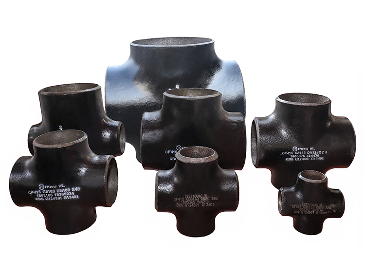
In industrial fluid dynamics and high-pressure piping network engineering, the structural distribution, redirection, and convergence of process media demand robust, leak-proof components. A Butt Weld Pipe Cross (also designated as a 4-way pipe fitting) serves as an orthogonal pipeline nexus, connecting four intersecting runs of pipe at perfect 90-degree vectors. By utilizing a full-penetration groove weld joint configuration (beveled per ASME B16.25 specifications), these fittings provide an uninterrupted metallurgical bond matching or exceeding the yield strength of the seamless or welded pipe shell itself. This manual covers extensive dimensional matrices, chemical verification parameters, and mechanical threshold criteria critical for piping stress analysts, procurement engineers, and quality control inspectors.
1. Classification by Interface Dimensions & Spatial Flow Profiles
The geometric interface of a pipe cross defines its ultimate fluid-dynamic footprint within a pipeline system. Any modification in port configuration shifts the localized pressure gradient, fluid turbulence, and erosion distribution profile across the fitting crotch radius. Fittings are fundamentally separated into two structural orientations:
1.1 Equal Cross (Straight Cross)
An Equal Cross maintains an identical nominal bore across all four points of access. For example, a DN200 equal cross means that the run axis and the branch axis possess perfectly matching interior dimensions. This absolute symmetry ensures that when fluid splits or merges, the localized volumetric velocity remains steady, minimizing the occurrence of kinetic energy conversion into thermal or vibrational noise. The center-to-end spatial dimensions are strictly locked in production to prevent geometric offset stack-up during complex spatial spool fabrications.
1.2 Reducing Cross
A Reducing Cross restricts the nominal diameters of the branch ports relative to the primary run header axis. This configuration is widely deployed in refinery manifolds where high-volume trunklines feed lower-volume utility headers or chemical reaction racks. Because the branch diameter is reduced, the fluid velocity spikes as it transitions into the smaller cross-sectional zone. To prevent severe wall thinning via erosion-corrosion phenomena, process designers limit fluid velocity boundaries using the API 14E empirical calculation limits to verify safe operational longevity under particulate-laden flow regimes.
2. Master Dimensional Data Tables (ASME B16.9 / Schedule Matrix)
The following data tables provide a comprehensive, structural, crawler-friendly index detailing the geometric specifications of Equal and Reducing Butt Weld Crosses. These dimensional values are crucial for generating precise CAD piping models and executing stress analysis via specialized software platforms.
| Nominal Pipe Size (NPS) | Outside Diameter at Bevel (mm) | Center-to-End Run (C) (mm) | Center-to-End Branch (M) (mm) | Approximate Weight (kg) – SCH 40 | Approximate Weight (kg) – SCH 80 |
|---|---|---|---|---|---|
| 1/2″ | 21.3 | 25.0 | 25.0 | 0.31 | 0.42 |
| 3/4″ | 26.7 | 29.0 | 29.0 | 0.48 | 0.64 |
| 1″ | 33.4 | 38.0 | 38.0 | 0.85 | 1.15 |
| 1-1/2″ | 48.3 | 57.0 | 57.0 | 1.92 | 2.65 |
| 2″ | 60.3 | 64.0 | 64.0 | 3.10 | 4.40 |
| 3″ | 88.9 | 86.0 | 86.0 | 6.45 | 9.20 |
| 4″ | 114.3 | 105.0 | 105.0 | 11.80 | 16.90 |
| 6″ | 168.3 | 143.0 | 143.0 | 26.10 | 40.20 |
| 8″ | 219.1 | 178.0 | 178.0 | 48.50 | 78.50 |
| 10″ | 273.0 | 216.0 | 216.0 | 81.00 | 134.00 |
| 12″ | 323.8 | 254.0 | 254.0 | 122.00 | 208.00 |
| 14″ | 355.6 | 279.0 | 279.0 | 159.00 | 272.00 |
| 16″ | 406.4 | 305.0 | 305.0 | 211.00 | 368.00 |
Table 2.1: ASME B16.9 Equal Cross standard geometric values and mass evaluations.
| Nominal Size (Run × Branch) | OD of Run (mm) | OD of Branch (mm) | Run Center-to-End (C) (mm) | Branch Center-to-End (M) (mm) | Weight (kg) – SCH 40 |
|---|---|---|---|---|---|
| 2″ × 1-1/2″ | 60.3 | 48.3 | 64.0 | 60.0 | 2.85 |
| 2″ × 1″ | 60.3 | 33.4 | 64.0 | 51.0 | 2.50 |
| 3″ × 2″ | 88.9 | 60.3 | 86.0 | 76.0 | 5.80 |
| 4″ × 3″ | 114.3 | 88.9 | 105.0 | 98.0 | 10.40 |
| 4″ × 2″ | 114.3 | 60.3 | 105.0 | 89.0 | 9.10 |
| 6″ × 4″ | 168.3 | 114.3 | 143.0 | 130.0 | 23.40 |
| 6″ × 3″ | 168.3 | 88.9 | 143.0 | 124.0 | 21.80 |
| 8″ × 6″ | 219.1 | 168.3 | 178.0 | 168.0 | 44.10 |
| 8″ × 4″ | 219.1 | 114.3 | 178.0 | 161.0 | 41.50 |
| 10″ × 8″ | 273.0 | 219.1 | 216.0 | 203.0 | 74.80 |
| 12″ × 10″ | 323.8 | 273.0 | 254.0 | 241.0 | 113.00 |
Table 2.2: ASME B16.9 Reducing Cross geometric layout dimensions and mass distributions.
3. Material Classifications & Structural Performance Index
Selecting the appropriate pipe material is critical to ensuring structural integrity in extreme environments. Choosing the incorrect grade can lead to localized cracking, sudden failure under high pressures, or rapid chemical corrosion.
3.1 Stainless Steel Structural Framework
Stainless steel crosses are highly alloyed with chromium and nickel to passivate the pipe surface, forming an inert chromium-oxide boundary film that protects against corrosion. Advanced grades also include molybdenum to resist localized pitting in high-salinity marine applications.
| Subtype | Standard & Grade | Key Metallurgical Structural Advantages | Target Application Directions |
|---|---|---|---|
| Austenitic | ASTM A403 WP304/L | 18% Cr-8% Ni composition. High ductile flexibility; exceptional weldability and economic cost matrix. | Sanitary lines; food processing facilities; beverage transfer loops; low-concentration organic acids. |
| Austenitic (Mo-Added) | ASTM A403 WP316/L | 2-3% Molybdenum addition. Prevents localized chloride pitting corrosion and stress cracking. | Seawater cooling loops; offshore chemical plants; pharmaceutical bioreactors; coastal storage tanks. |
| Duplex | ASTM A815 S31803 (2205) | Balanced 50% Ferrite / 50% Austenite microstructure. Yields 2x the structural yield limits of standard 304 series. | Subsea flow lines; sour gas processing complexes (H_{2}S > 50\text{ ppm}); desalination systems. |
| Super Duplex | ASTM A815 S32750 (2507) | Highly alloyed status providing \text{PREN} \ge 42. Immune to cavitation pitting under extreme fluid velocities. | Flue-gas desulfurization loops; high-concentration industrial acid pipelines; deep subsea production manifolds. |
Table 3.1: Stainless steel subtype metallurgical performance parameters and application mappings.
3.2 Carbon Steel Structural Framework
Carbon steel crosses deliver excellent load-bearing capacity, outstanding impact toughness, and wide temperature applicability, making them an industry standard for cross-country oil pipelines and chemical utilities.
| Subtype | Standard & Grade | Key Structural Mechanical Advantages | Target Application Directions |
|---|---|---|---|
| Mild Steel | ASTM A234 WPB | Optimum balance of tensile strength and weldability. Highly versatile, multi-thickness commercial availability. | Cross-country water trunk lines; long-distance oil transport spools; industrial municipal utilities. |
| Medium Carbon | ASTM A106 Grade C | Elevated carbon thresholds providing improved yield capabilities under extreme hoop-stress variables. | High-pressure gas grid connections; processing facility high-pressure headers; heavy machinery piping manifolds. |
| Low-Temp Carbon | ASTM A333 Grade 6 | Fine-grain killed structure. Confirms impact test survival metrics at sub-zero cold points down to -45°C. | Arctic atmospheric gas plants; low-temperature expansion racks; cryogenic cooling sub-loops. |
Table 4.1: Carbon steel mechanical grading limits and system engineering assignments.
4. Comprehensive Ladle Chemical Element Distribution Profiles
The precise element percentage mapping below determines the crystalline phase change limits during full-penetration welding processes. These values represent maximum thresholds unless specified as a range.
| Material Grade Standard | C % | Si % | Mn % | P % | S % | Cr % | Mo % | Ni % | Other % |
|---|---|---|---|---|---|---|---|---|---|
| ASTM A234 WPB | 0.30 max | 0.10 min | 0.29-1.06 | 0.050 | 0.058 | 0.40 max | 0.15 max | 0.40 max | Cu ≤ 0.40 |
| ASTM A106 Grade C | 0.35 max | 0.10 min | 0.29-1.06 | 0.035 | 0.035 | 0.40 max | 0.15 max | 0.40 max | V ≤ 0.08 |
| ASTM A333 Grade 6 | 0.30 max | 0.10 min | 0.29-1.06 | 0.025 | 0.025 | 0.30 max | 0.12 max | 0.40 max | Al fine grain |
| WP304L (ASTM A403) | 0.030 max | 1.00 max | 2.00 max | 0.045 | 0.030 | 18.0-20.0 | — | 8.0-12.0 | N ≤ 0.10 |
| WP316L (ASTM A403) | 0.030 max | 1.00 max | 2.00 max | 0.045 | 0.030 | 16.0-18.0 | 2.00-3.00 | 10.0-14.0 | N ≤ 0.10 |
| WP22 (Alloy Steel) | 0.05-0.15 | 0.50 max | 0.30-0.60 | 0.040 | 0.040 | 2.00-2.50 | 0.87-1.13 | — | — |
| WP91 (Alloy Steel) | 0.08-0.12 | 0.20-0.50 | 0.30-0.60 | 0.020 | 0.010 | 8.00-9.50 | 0.85-1.05 | 0.40 max | V: 0.18-0.25; Nb: 0.06-0.10 |
Table 5.1: Chemical elemental restrictions across industrial standard grades.
5. Certified Material Mechanical Property Threshold Limits
Mechanical properties define the physical response of a component under pressurized structural loads. In high-stakes processing plants, these parameters dictate individual pipeline safety margins.
| Material Evaluation Grade | Tensile Strength Rm (MPa) | Yield Strength ReH (MPa) min | Elongation A5 (%) min | Hardness Brinell (HB) max | Charpy V-Notch Impact (J) min |
|---|---|---|---|---|---|
| ASTM A234 WPB | 415 – 550 | 240 | 30 | 197 | — |
| ASTM A106 Grade C | 485 min | 275 | 20 | 210 | — |
| ASTM A333 Grade 6 | 415 min | 240 | 22 | 190 | 20 J @ -45°C |
| WP304L (A403) | 485 min | 170 | 28 | 192 | — |
| WP316L (A403) | 485 min | 170 | 28 | 192 | — |
| WP22 (A234) | 415 – 585 | 205 | 30 | 179 | — |
| WP91 (A234) | 590 – 760 | 415 | 20 | 248 | 41 J @ 20°C |
Table 6.1: Core mechanical profiles and certified tough resistance testing metrics.
6. Advanced Custom Manufacturing & Hot-Push Forming Process
The production of seamless butt-weld crosses relies on a precise thermo-mechanical sequence. Below is the step-by-step manufacturing workflow executed within automated industrial mills:
Requirements Confirmation & CAD Layout Generation
Billet Slicing & Edge Conditioning
Internal Matrix Lubricant Spray Application
Medium-Frequency Induction Hot-Push Forming
Controlled Mist Satiation & Bevel Facing Machining
100% Nondestructive Testing (NDT) Evaluation
Centrifugal Shot Blast & Protective Coating
End Cap Isolation, Mill Certification & Packaging


You must be logged in to post a comment.