

ขนาดข้ามท่อเชื่อมชน & ข้อมูลจำเพาะทางเทคนิค
คู่มืออ้างอิงทางวิศวกรรมขั้นสูงสุดสำหรับ ASME B16.9 และ EN 10253 สี่ทาง อุปกรณ์ท่อ. ศูนย์ข้อมูลที่สมบูรณ์ซึ่งครอบคลุมความคลาดเคลื่อนทางเรขาคณิต, เมทริกซ์โลหะวิทยา, การจัดอันดับความดัน, และกระบวนการผลิตแบบกดร้อนขั้นสูง.
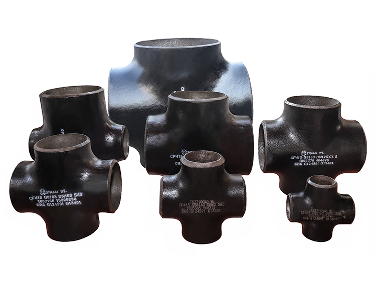
ในพลศาสตร์ของไหลทางอุตสาหกรรมและวิศวกรรมเครือข่ายท่อแรงดันสูง, การกระจายตัวของโครงสร้าง, การเปลี่ยนเส้นทาง, และการบรรจบกันของความต้องการสื่อกระบวนการที่แข็งแกร่ง, ส่วนประกอบป้องกันการรั่วซึม. A ข้ามท่อเชื่อมชน (กำหนดให้เป็นทาง 4 ทิศทางด้วย การติดตั้งท่อ) ทำหน้าที่เป็นจุดเชื่อมโยงไปป์ไลน์มุมฉาก, เชื่อมต่อท่อสี่ท่อที่ตัดกันที่เวกเตอร์ 90 องศาที่สมบูรณ์แบบ. โดยใช้โครงข้อต่อเชื่อมร่องเจาะเต็ม (เอียงตามข้อกำหนด ASME B16.25), อุปกรณ์เหล่านี้ให้การจับคู่พันธะทางโลหะวิทยาอย่างต่อเนื่องหรือเกินความแข็งแรงของผลผลิตของเปลือกท่อไร้รอยต่อหรือแบบเชื่อมเอง. คู่มือนี้ครอบคลุมถึงเมทริกซ์มิติที่กว้างขวาง, พารามิเตอร์การตรวจสอบทางเคมี, และเกณฑ์เกณฑ์ทางกลที่สำคัญสำหรับนักวิเคราะห์ความเครียดของท่อ, วิศวกรฝ่ายจัดซื้อ, และผู้ตรวจสอบการควบคุมคุณภาพ.
1. การจำแนกประเภทตามขนาดอินเทอร์เฟซ & โปรไฟล์การไหลเชิงพื้นที่
ส่วนต่อประสานทางเรขาคณิตของแนวขวางของไปป์จะกำหนดรอยเท้าแบบไดนามิกของของไหลขั้นสูงสุดภายในระบบไปป์ไลน์. การปรับเปลี่ยนใดๆ ในการกำหนดค่าพอร์ตจะเปลี่ยนระดับความดันที่แปลเป็นภาษาท้องถิ่น, ความปั่นป่วนของของไหล, และโปรไฟล์การกระจายการกัดเซาะตลอดรัศมีเป้าที่เหมาะสม. ข้อต่อต่างๆ ถูกแยกโดยพื้นฐานออกเป็นสองทิศทางของโครงสร้าง:
1.1 ข้ามเท่ากับ (ตรงข้าม)
Equal Cross จะรักษารูเจาะที่เหมือนกันตลอดจุดเข้าถึงทั้งสี่จุด. ตัวอย่างเช่น, กากบาทที่เท่ากันของ DN200 หมายความว่าแกนรันและแกนสาขามีขนาดภายในที่เข้ากันอย่างลงตัว. ความสมมาตรสัมบูรณ์นี้ช่วยให้แน่ใจว่าเมื่อของไหลแยกหรือรวมเข้าด้วยกัน, ความเร็วเชิงปริมาตรที่แปลเป็นภาษาท้องถิ่นยังคงคงที่, ลดการเกิดการแปลงพลังงานจลน์เป็นเสียงรบกวนจากความร้อนหรือการสั่นสะเทือน. มิติเชิงพื้นที่จากศูนย์กลางถึงปลายถูกล็อคอย่างเข้มงวดในการผลิตเพื่อป้องกันการซ้อนออฟเซ็ตทางเรขาคณิตในระหว่างการผลิตสปูลเชิงพื้นที่ที่ซับซ้อน.
1.2 ลดขน
เครื่องหมายรีดิวซ์ครอสจะจำกัดเส้นผ่านศูนย์กลางระบุของพอร์ตสาขาที่สัมพันธ์กับแกนส่วนหัวของรันหลัก. การกำหนดค่านี้ถูกนำไปใช้อย่างกว้างขวางในท่อร่วมโรงกลั่น โดยที่สายหลักที่มีปริมาณมากป้อนส่วนหัวของยูทิลิตี้ที่มีปริมาณน้อยกว่าหรือชั้นวางปฏิกิริยาเคมี. เนื่องจากเส้นผ่านศูนย์กลางกิ่งลดลง, ความเร็วของของไหลจะเพิ่มขึ้นอย่างรวดเร็วเมื่อเปลี่ยนเข้าสู่เขตหน้าตัดที่เล็กกว่า. เพื่อป้องกันผนังบางอย่างรุนแรงจากการกัดเซาะ-การกัดกร่อน, ผู้ออกแบบกระบวนการจำกัดขอบเขตความเร็วของเหลวโดยใช้ขีดจำกัดการคำนวณเชิงประจักษ์ของ API 14E เพื่อตรวจสอบอายุการใช้งานที่ยาวนานและปลอดภัยภายใต้ระบบการไหลของอนุภาคที่เต็มไปด้วยภาระ.
2. ตารางข้อมูลมิติหลัก (ASME B16.9 / ตารางเมทริกซ์)
ตารางข้อมูลต่อไปนี้ให้ข้อมูลที่ครอบคลุม, โครงสร้าง, ดัชนีที่เป็นมิตรกับโปรแกรมรวบรวมข้อมูลซึ่งมีรายละเอียดข้อกำหนดทางเรขาคณิตของ Equal และ Reduction Butt Weld Crosses. ค่ามิติเหล่านี้มีความสำคัญอย่างยิ่งต่อการสร้างแบบจำลองการวางท่อ CAD ที่แม่นยำ และดำเนินการวิเคราะห์ความเครียดผ่านแพลตฟอร์มซอฟต์แวร์เฉพาะทาง.
| Nominal ท่อขนาด (NPS) | เส้นผ่านศูนย์กลางภายนอกที่มุมเอียง (มม.) | การวิ่งจากศูนย์กลางถึงจุดสิ้นสุด (C) (มม.) | สาขาเซ็นเตอร์ทูเอนด์ (ม) (มม.) | น้ำหนักโดยประมาณ (kg) – กำหนด 40 | น้ำหนักโดยประมาณ (kg) – กำหนด 80 |
|---|---|---|---|---|---|
| 1/2″ | 21.3 | 25.0 | 25.0 | 0.31 | 0.42 |
| 3/4″ | 26.7 | 29.0 | 29.0 | 0.48 | 0.64 |
| 1″ | 33.4 | 38.0 | 38.0 | 0.85 | 1.15 |
| 1-1/2″ | 48.3 | 57.0 | 57.0 | 1.92 | 2.65 |
| 2″ | 60.3 | 64.0 | 64.0 | 3.10 | 4.40 |
| 3″ | 88.9 | 86.0 | 86.0 | 6.45 | 9.20 |
| 4″ | 114.3 | 105.0 | 105.0 | 11.80 | 16.90 |
| 6″ | 168.3 | 143.0 | 143.0 | 26.10 | 40.20 |
| 8″ | 219.1 | 178.0 | 178.0 | 48.50 | 78.50 |
| 10″ | 273.0 | 216.0 | 216.0 | 81.00 | 134.00 |
| 12″ | 323.8 | 254.0 | 254.0 | 122.00 | 208.00 |
| 14″ | 355.6 | 279.0 | 279.0 | 159.00 | 272.00 |
| 16″ | 406.4 | 305.0 | 305.0 | 211.00 | 368.00 |
ตาราง 2.1: ASME B16.9 ค่าเรขาคณิตมาตรฐาน Equal Cross และการประเมินมวล.
| ขนาด (วิ่ง×สาขา) | OD ของการรัน (มม.) | OD ของสาขา (มม.) | เรียกใช้จากศูนย์กลางถึงจุดสิ้นสุด (C) (มม.) | สาขาจากศูนย์ถึงปลายทาง (ม) (มม.) | น้ำหนัก (kg) – กำหนด 40 |
|---|---|---|---|---|---|
| 2″ × 1-1/2″ | 60.3 | 48.3 | 64.0 | 60.0 | 2.85 |
| 2″ × 1″ | 60.3 | 33.4 | 64.0 | 51.0 | 2.50 |
| 3″ × 2″ | 88.9 | 60.3 | 86.0 | 76.0 | 5.80 |
| 4″ × 3″ | 114.3 | 88.9 | 105.0 | 98.0 | 10.40 |
| 4″ × 2″ | 114.3 | 60.3 | 105.0 | 89.0 | 9.10 |
| 6″ × 4″ | 168.3 | 114.3 | 143.0 | 130.0 | 23.40 |
| 6″ × 3″ | 168.3 | 88.9 | 143.0 | 124.0 | 21.80 |
| 8″ × 6″ | 219.1 | 168.3 | 178.0 | 168.0 | 44.10 |
| 8″ × 4″ | 219.1 | 114.3 | 178.0 | 161.0 | 41.50 |
| 10″ × 8″ | 273.0 | 219.1 | 216.0 | 203.0 | 74.80 |
| 12″ × 10″ | 323.8 | 273.0 | 254.0 | 241.0 | 113.00 |
ตาราง 2.2: ASME B16.9 การลดขนาดเค้าโครงทางเรขาคณิตข้ามและการกระจายมวล.
3. การจำแนกประเภทวัสดุ & ดัชนีประสิทธิภาพของโครงสร้าง
การเลือกวัสดุท่อที่เหมาะสมถือเป็นสิ่งสำคัญในการรับประกันความสมบูรณ์ของโครงสร้างในสภาพแวดล้อมที่รุนแรง. การเลือกเกรดที่ไม่ถูกต้องอาจทำให้เกิดการแตกร้าวเฉพาะจุดได้, ความล้มเหลวอย่างกะทันหันภายใต้แรงกดดันสูง, หรือการกัดกร่อนของสารเคมีอย่างรวดเร็ว.
3.1 กรอบโครงสร้างสแตนเลส
ไม้กางเขนสแตนเลสผสมโครเมียมและนิกเกิลสูงเพื่อกั้นผิวท่อ, สร้างฟิล์มขอบเขตโครเมียมออกไซด์เฉื่อยที่ป้องกันการกัดกร่อน. เกรดขั้นสูงยังรวมถึงโมลิบดีนัมเพื่อต้านทานการเกิดรูพรุนในการใช้งานทางทะเลที่มีความเค็มสูง.
| ชนิดย่อย | มาตรฐาน & เกรด | ข้อได้เปรียบทางโครงสร้างทางโลหการที่สำคัญ | ทิศทางการสมัครเป้าหมาย |
|---|---|---|---|
| ออสเตนนิติก | ASTM A403 WP304/ลิตร | 18% องค์ประกอบของ Cr-8% Ni. มีความยืดหยุ่นสูง; ความสามารถในการเชื่อมที่ยอดเยี่ยมและเมทริกซ์ต้นทุนทางเศรษฐกิจ. | เส้นสุขาภิบาล; สิ่งอำนวยความสะดวกการแปรรูปอาหาร; ลูปการถ่ายโอนเครื่องดื่ม; กรดอินทรีย์ที่มีความเข้มข้นต่ำ. |
| ออสเตนนิติก (Mo-เพิ่ม) | ASTM A403 WP316/ลิตร | 2-3% การเติมโมลิบดีนัม. ป้องกันการกัดกร่อนแบบรูพรุนของคลอไรด์เฉพาะจุดและการแตกร้าวจากความเค้น. | วงจรระบายความร้อนด้วยน้ำทะเล; โรงงานเคมีนอกชายฝั่ง; เครื่องปฏิกรณ์ชีวภาพทางเภสัชกรรม; ถังเก็บน้ำชายฝั่ง. |
| พิมพ์กลับหน้า | S31803 ASTM A815 (2205) | สมดุล 50% เฟอร์ไรท์ / 50% โครงสร้างจุลภาคของออสเทนไนต์. ให้ผลตอบแทน 2 เท่าของขีดจำกัดผลตอบแทนเชิงโครงสร้างตามมาตรฐาน 304 ชุด. | เส้นไหลใต้ทะเล; คอมเพล็กซ์การแปรรูปก๊าซเปรี้ยว (ชม_{2}S > 50\ข้อความ{ PPM}); ระบบกลั่นน้ำทะเล. |
| ซูเปอร์ดูเพล็กซ์ | มาตรฐาน ASTM A815 S32750 (2507) | ให้สถานะโลหะผสมสูง \ข้อความ{ไม้} \ge 42. ภูมิคุ้มกันต่อการเกิดโพรงโพรงอากาศภายใต้ความเร็วของของไหลที่รุนแรง. | วงจรกำจัดซัลเฟอร์ไรเซชันของก๊าซไอเสีย; ท่อส่งกรดอุตสาหกรรมที่มีความเข้มข้นสูง; แหล่งผลิตใต้ทะเลลึก. |
ตาราง 3.1: พารามิเตอร์ประสิทธิภาพโลหะวิทยาชนิดย่อยสแตนเลสและการแมปแอปพลิเคชัน.
3.2 กรอบโครงสร้างเหล็กคาร์บอน
ไม้กางเขนเหล็กกล้าคาร์บอนให้ความสามารถในการรับน้ำหนักที่ดีเยี่ยม, ความเหนียวทนแรงกระแทกที่โดดเด่น, และการบังคับใช้อุณหภูมิที่กว้าง, ทำให้เป็นมาตรฐานอุตสาหกรรมสำหรับท่อส่งน้ำมันข้ามประเทศและสาธารณูปโภคด้านเคมี.
| ชนิดย่อย | มาตรฐาน & เกรด | ข้อดีทางกลโครงสร้างที่สำคัญ | ทิศทางการสมัครเป้าหมาย |
|---|---|---|---|
| เหล็กกล้า | การเดินทางมาตรฐาน ASTM A234 | ความสมดุลที่เหมาะสมของความต้านทานแรงดึงและความสามารถในการเชื่อม. มีความหลากหลายสูง, ความพร้อมใช้งานเชิงพาณิชย์ที่มีความหนาหลายระดับ. | แนวท่อส่งน้ำข้ามประเทศ; หลอดขนส่งน้ำมันทางไกล; สาธารณูปโภคเทศบาลอุตสาหกรรม. |
| คาร์บอนปานกลาง | ASTM A106 เกรด C | เกณฑ์คาร์บอนที่สูงขึ้นช่วยเพิ่มความสามารถในการให้ผลผลิตภายใต้ตัวแปรความเครียดห่วงที่รุนแรง. | การเชื่อมต่อโครงข่ายก๊าซแรงดันสูง; ส่วนหัวแรงดันสูงของสถานที่ประมวลผล; ท่อร่วมเครื่องจักรกลหนัก. |
| คาร์บอนอุณหภูมิต่ำ | ASTM A333 เกรด 6 | โครงสร้างที่ถูกฆ่าแบบละเอียด. ยืนยันเมตริกการอยู่รอดของการทดสอบแรงกระแทกที่จุดเย็นต่ำกว่าศูนย์จนถึง -45°C. | โรงผลิตก๊าซบรรยากาศอาร์กติก; ชั้นวางขยายอุณหภูมิต่ำ; ลูปย่อยการทำความเย็นแบบไครโอเจนิกส์. |
ตาราง 4.1: ขีดจำกัดการให้เกรดเชิงกลของเหล็กกล้าคาร์บอน และงานวิศวกรรมระบบ.
4. โปรไฟล์การกระจายองค์ประกอบทางเคมีของทัพพีที่ครอบคลุม
การแมปเปอร์เซ็นต์องค์ประกอบที่แม่นยำด้านล่างจะกำหนดขีดจำกัดการเปลี่ยนแปลงเฟสของผลึกในระหว่างกระบวนการเชื่อมแบบเจาะเต็ม. ค่าเหล่านี้แสดงถึงเกณฑ์สูงสุด เว้นแต่จะระบุเป็นช่วง.
| มาตรฐานเกรดวัสดุ | C % | ศรี % | Mn % | P % | S % | Cr % | Mo % | Ni % | อื่น ๆ % |
|---|---|---|---|---|---|---|---|---|---|
| การเดินทางมาตรฐาน ASTM A234 | 0.30 สูงสุด | 0.10 นาที | 0.29-1.06 | 0.050 | 0.058 | 0.40 สูงสุด | 0.15 สูงสุด | 0.40 สูงสุด | ลูกบาศ์ก ≤ 0.40 |
| ASTM A106 เกรด C | 0.35 สูงสุด | 0.10 นาที | 0.29-1.06 | 0.035 | 0.035 | 0.40 สูงสุด | 0.15 สูงสุด | 0.40 สูงสุด | วี ≤ 0.08 |
| ASTM A333 เกรด 6 | 0.30 สูงสุด | 0.10 นาที | 0.29-1.06 | 0.025 | 0.025 | 0.30 สูงสุด | 0.12 สูงสุด | 0.40 สูงสุด | อัลเกรนเกรน |
| WP304L (ASTM A403) | 0.030 สูงสุด | 1.00 สูงสุด | 2.00 สูงสุด | 0.045 | 0.030 | 18.0-20.0 | - | 8.0-12.0 | ยังไม่มีข้อความ ≤ 0.10 |
| WP316L (ASTM A403) | 0.030 สูงสุด | 1.00 สูงสุด | 2.00 สูงสุด | 0.045 | 0.030 | 16.0-18.0 | 2.00-3.00 | 10.0-14.0 | ยังไม่มีข้อความ ≤ 0.10 |
| WP22 (โลหะผสมเหล็ก) | 0.05-0.15 | 0.50 สูงสุด | 0.30-0.60 | 0.040 | 0.040 | 2.00-2.50 | 0.87-1.13 | - | - |
| WP91 (โลหะผสมเหล็ก) | 0.08-0.12 | 0.20-0.50 | 0.30-0.60 | 0.020 | 0.010 | 8.00-9.50 | 0.85-1.05 | 0.40 สูงสุด | V: 0.18-0.25; Nb: 0.06-0.10 |
ตาราง 5.1: ข้อจำกัดด้านองค์ประกอบทางเคมีสำหรับเกรดมาตรฐานอุตสาหกรรม.
5. ขีดจำกัดเกณฑ์คุณสมบัติทางกลของวัสดุที่ผ่านการรับรอง
สมบัติทางกลเป็นตัวกำหนดการตอบสนองทางกายภาพของส่วนประกอบภายใต้ภาระโครงสร้างที่มีแรงดัน. ในโรงงานแปรรูปที่มีเดิมพันสูง, พารามิเตอร์เหล่านี้กำหนดระยะขอบด้านความปลอดภัยของไปป์ไลน์แต่ละรายการ.
| เกรดการประเมินวัสดุ | ความต้านแรงดึง Rม (MPa) | ความแข็งแรงของผลผลิตอาร์เอ๊ะ (MPa) นาที | Elongation น5 (%) นาที | ความแข็งบริเนล (HB) สูงสุด | ชาร์ปี V-Notch Impact (เจ) นาที |
|---|---|---|---|---|---|
| การเดินทางมาตรฐาน ASTM A234 | 415 – 550 | 240 | 30 | 197 | - |
| ASTM A106 เกรด C | 485 นาที | 275 | 20 | 210 | - |
| ASTM A333 เกรด 6 | 415 นาที | 240 | 22 | 190 | 20 D @ -45°C |
| WP304L (A403) | 485 นาที | 170 | 28 | 192 | - |
| WP316L (A403) | 485 นาที | 170 | 28 | 192 | - |
| WP22 (A234) | 415 – 585 | 205 | 30 | 179 | - |
| WP91 (A234) | 590 – 760 | 415 | 20 | 248 | 41 D @ 20°C |
ตาราง 6.1: โปรไฟล์เชิงกลหลักและเมตริกการทดสอบความต้านทานที่แข็งแกร่งที่ผ่านการรับรอง.
6. การผลิตแบบกำหนดเองขั้นสูง & กระบวนการขึ้นรูปแบบกดร้อน
การผลิตไม้กางเขนเชื่อมชนแบบไร้ตะเข็บต้องอาศัยลำดับทางเทอร์โมกลที่แม่นยำ. ด้านล่างนี้คือขั้นตอนการผลิตทีละขั้นตอนที่ดำเนินการภายในโรงงานอุตสาหกรรมแบบอัตโนมัติ:
การยืนยันข้อกำหนด & การสร้างเค้าโครง CAD
การหั่นบิลเล็ต & การปรับสภาพขอบ
การใช้งานสเปรย์หล่อลื่นเมทริกซ์ภายใน
การขึ้นรูปกดร้อนด้วยการเหนี่ยวนำความถี่ปานกลาง
ควบคุมความอิ่มของหมอก & การกลึงหันหน้าไปทางเอียง
100% nondestructive การทดสอบ (NDT) การประเมิน
ระเบิดแรงเหวี่ยง & เคลือบป้องกัน
การแยกฝาท้าย, การรับรองโรงสี & บรรจุภัณฑ์


คุณจะต้องเป็น เข้าสู่ระบบ แสดงความคิดเห็น.