
ASTM & EN Standardized Structural Hollow Sections
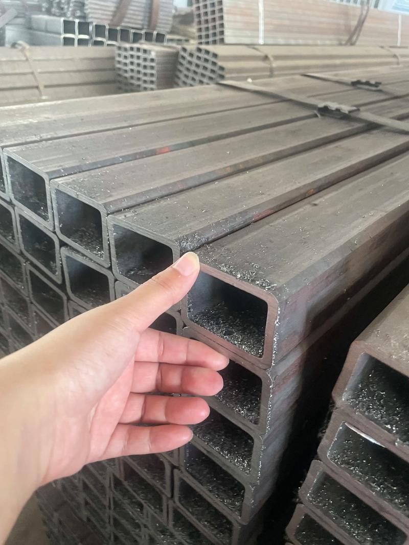
Carbon Steel Rectangular & Square Pipe
Premium Cold-Formed and Hot-Finished Structural Hollow Sections (SHS / RHS) engineered for high-load steel frames, heavy industrial manufacturing, and civil grid infrastructure.
1. Engineering Overview of Carbon Steel Rectangular Pipes
Carbon steel rectangular and square pipes Often specified as Rectangular Hollow Sections (RHS) or Square Hollow Sections (SHS), these products combine the structural efficiency of high-strength carbon steel with a geometric shape that maximizes rotational stiffness, torsional resistance, and flat-surface load distribution. This comprehensive technical document outlines the metallurgy, production methodologies, and extensive dimensional standards that govern modern carbon steel hollow section manufacturing.
Manufactured via either high-frequency Electric Resistance Welding (ERW) or seamless extrusion methods, these tubes undergo strict dimensional verification, thermal processing, and surface protective treatments. By adhering to rigorous ASTM and EN standards, they deliver predictable performance under heavy mechanical tension, high seismic stress, and severe atmospheric environments.
2. Chemical Composition Limits of Structural Materials
The specific metallurgical limits of alloying elements determine the physical weldability, impact toughness, and mechanical integrity of hollow sections. Below is the detailed elemental breakdown for major ASTM and EN structural steel specifications.
| Grade / Element Specification | Carbon (C)% Max | Silicon (Si)% Max | Manganese (Mn)% Max | Phosphorus (P)% Max | Sulfur (S)% Max | Nitrogen (N)% Max |
|---|---|---|---|---|---|---|
| ASTM A500 Gr. B | 0.23% | — | 1.35% | 0.045% | 0.045% | — |
| S235JRH (1.0039) | 0.17% | — | 1.40% | 0.045% | 0.045% | 0.009% |
| S275J0H (1.0149) | 0.20% | — | 1.50% | 0.040% | 0.040% | 0.009% |
| S275J2H (1.0138) | 0.20% | — | 1.50% | 0.035% | 0.035% | — |
| S355J0H (1.0547) | 0.22% | 0.55% | 1.60% | 0.040% | 0.040% | 0.009% |
| S355J2H (1.0576) | 0.22% | 0.55% | 1.60% | 0.035% | 0.035% | — |
3. Structural Mechanical Strength Profiles
To ensure safety factors are respected in load-bearing engineering calculations, the minimum yield and tensile limits must be rigorously cross-referenced across design codes.
| Specification Standards | Yield Strength Min. (MPa / ksi) | Tensile Strength Range (MPa / ksi) | Minimum Elongation % | Impact Energy Charpy V-Notch (J) |
|---|---|---|---|---|
| ASTM A500 Grade B | 315 MPa (46 ksi) | 400 MPa (58 target) | 23% | — |
| S235JRH (1.0039) | 235 MPa | 360 – 510 MPa | 26% (Longitudinal) | 27 Joules @ +20°C |
| S275J0H (1.0149) | 275 MPa | 410 – 560 MPa | 22% (Longitudinal) | 27 Joules @ 0°C |
| S355J2H (1.0576) | 355 MPa | 490 – 630 MPa | 22% (Longitudinal) | 27 Joules @ -20°C |
4. Structural Hollow Section Nomenclature Decoding
“S” Designation Prefix
Represents “STEEL FOR STRUCTURAL APPLICATIONS”. This code ensures the batch has been certified for mechanical load-bearing functions.
Yield Value Indication
The standard numerical value (e.g., 235, 275, 355) represents the minimum required yield value (MPa) for wall thicknesses ≤ 16 mm.
Impact Code “J2”
Specifies a minimum Charpy V-notch impact energy absorption capacity of 27 Joules at -20°C, indicating high resistance to cold-temperature fracture.
5. International Standard Equivalency Grid
To assist project procurement officers in sourcing equivalent materials globally, the following table details structural grades under European (EN), French (NF), German (DIN), British (BS), and Italian (UNI) systems.
| EN 10210 / 10219 | NF A 49501 / 35501 | DIN 17100 / 17123 | BS 4360 | UNI 7806 |
|---|---|---|---|---|
| S235JRH | E 24-2 | St 37.2 | Fe 360 BS | Fe 360 |
| S275J0H | E 28-3 | St 44.3 | U43 C | Fe 430 C |
| S355J2H | E 36-4 | St 52.3 N | 50 D | Fe 510 D |
6. Production Process Classification & Structural Class Systems
Depending on the target mechanical requirements and wall thickness configurations, square and rectangular pipes are produced using specific forming and thermal techniques. We divide hollow manufacturing into three main categories: seamless extruded hollow sections, high-frequency Electric Resistance Welded (ERW) sections, and specialized Submerged Arc Welded (SAW) formats.
7. Dimensional Ranges: Rectangular Hollow Section Matrix
Our automated forming mills can customize rectangular hollow geometries according to precise project configurations. Below is a comprehensive engineering dimension-to-thickness chart.
| Square Hollow Section Size (mm) | Rectangular Hollow Section Size (mm) | Standard Wall Thickness (mm) |
|---|---|---|
| 20 x 20 / 25 x 25 / 30 x 30 | 20 x 40 / 30 x 40 | 1.7 – 2.75 mm |
| 40 x 40 / 50 x 50 | 30 x 50 / 25 x 50 / 30 x 60 / 40 x 60 | 1.2 – 4.75 mm |
| 60 x 60 | 50 x 70 / 40 x 80 / 40 x 50 | 1.2 – 5.75 mm |
| 80 x 80 / 90 x 90 | 60 x 100 / 50 x 100 / 120 x 60 / 100 x 80 | 1.5 – 8.0 mm |
| 100 x 100 / 120 x 120 | 120 x 80 / 160 x 80 / 150 x 100 | 2.5 – 10.0 mm |
| 200 x 200 / 250 x 250 | 200 x 150 / 250 x 150 / 300 x 200 | 3.5 – 12.0 mm |
| 400 x 400 / 500 x 500 | 450 x 300 / 500 x 300 / 400 x 600 | 4.5 – 20.0 mm |
8. Surface Finish Systems and Anti-Corrosion Options
The working atmosphere determines the optimal choice of surface protectant. Below is our standard treatment range designed to prevent superficial iron oxide formation.
| Surface Treatment Type | Technical Coating Density / Thickness | Primary Protection Objective |
|---|---|---|
| Hot-Dip Galvanized (HDG) | Zinc Coating: 200 – 600 g/m² (≥ 86 μm) | Full galvanic alloy protection for severe industrial and coastal marine climates. |
| Pre-Galvanized (Continuous Coil) | Zinc Coating: 40 – 80 g/m² | Cost-effective indoor frames, structural support grids, and standard racking. |
| Organic Anti-Rust Oil / Soluble Lacquer | Temporary transparent polymer film | In-transit storage protection, facilitating quick on-site welding preparation. |
| Powder Coated / Epoxy Painted | Dry film thickness up to 120 μm | Decorative structural profiles with high abrasion resistance and UV stability. |
9. Crucial Control Parameters During Hollow Section Fabrication
Achieving straight, square-edged carbon steel rectangular profiles requires continuous process adjustments. Our mill prioritizes three key parameters:
- Continuous Roll Forming Calibration: Controlling edge alignment to eliminate radial twisting and excessive corner radii variations.
- Solid-State Induction Welding (HF): Monitoring joint temperature profiles to prevent weld line inclusions or pinhole cracking.
- Post-Weld In-Line Sizing & Thermal Treatment: Stabilizing internal stresses using localized induction normalization along the weld zone.
10. Shipping, Bundling, and Seaworthy Packaging Standard
Heavy cargo ocean transportation exposes steel profiles to mechanical impacts and humid environments. We enforce a strict preparation standard for all containerized shipments.
Hexagonal Bundling System
Pipes are arranged in solid hexagonal bundles, tightly wrapped with multiple steel straps to ensure stable handling during crane loading operations.
Protective End Caps
Heavy-duty plastic bevel protectors are fitted to hollow ends to keep moisture, debris, and marine salt air from infiltrating the unprotected inner core.
Moisture Barrier Wrapping
Pre-galvanized cargo receives an outer layer of woven plastic wrapping to prevent water ingress and mitigate white rust during sea transits.
11. Advanced Mechanical Loading Calculations & Cross-Section Engineering
Civil and industrial engineers rely on accurate geometric parameters to calculate load-carrying capacities, deflections, and torsional buckling thresholds. Standardized rectangular hollow configurations (RHS) provide superior performance under multi-axis structural stresses.
The localized moment of inertia ($I_x$) and the elastic section modulus ($S_x$) of our structural hollow sections are calculated using these standard formulas:
The localized moment of inertia (\(I_x\)) and the elastic section modulus (\(S_x\)) of our structural hollow sections are calculated using these standard formulas:
\[ I_x = \frac{B H^3 – b h^3}{12} \] \[ S_x = \frac{B H^3 – b h^3}{6H} \]
Where \(B\) and \(H\) represent the outer envelope width and height, and \(b\) and \(h\) represent the inner width and height.
Where $B$ and $H$ represent the outer envelope width and height, $b$ and $h$ represent the inner hollow dimensions, and $A$ denotes the total structural cross-sectional area of the profile.
12. Global Engineering Compliance and Manufacturing Certification
Our manufacturing lines operate under audited quality control systems to meet major international structural steel standards.
| Standard Code | Geographical Authority | Primary Application Scope | Material Testing Certification |
|---|---|---|---|
| ASTM A500 | North America (ANSI) | Cold-formed welded and seamless carbon steel structural tubing in round and shapes. | EN 10204 3.1 Certified |
| EN 10219 | European Union (CEN) | Cold-formed welded structural hollow sections of non-alloy and fine grain steels. | CE EN 1090-1 Compliant |
| JIS G3466 | Japan (JSA) | Carbon steel square and rectangular tubes for general structural purposes. | JIS Mark Certified |
| GB/T 6728 | China (SAC) | Cold-formed steel hollow sections for general structural purposes. | MTC ISO 9001 Audited |
13. Specialized Welding Joint Configurations and Design
Weld design is critical when joining hollow sections to plates, columns, or adjacent members. Proper geometry ensures effective stress transfer and prevents localized stress concentrations.
Butt Welds with Backing
Designed for high-stress splice connections, utilizing internal backing rings or bars to guarantee complete joint penetration (CJP) under dynamic fatigue loads.
Fillet Welded Sleeve Joint
An efficient option for low-load framing, offering quick alignment adjustments prior to depositing structural weld passes.
Reinforced Gusset Plates
Adding external gussets at heavy connection nodes spreads rotational stress away from the pipe’s outer walls, preventing localized buckling.
14. Manufacturing Tolerances for Rectangular Steel Pipes
To ensure accurate fit-up in automated laser cutting and assembly lines, we maintain strict dimensional tolerances on all production runs.
| Geometric Parameter | Standard Tolerance Allowed (EN 10219) | Standard Tolerance Allowed (ASTM A500) |
|---|---|---|
| Outer Dimensions (B, H) | ± 1% (min. ± 0.5 mm) | ± 0.75% of specified dimension |
| Wall Thickness (T) | ± 10% for T ≤ 5mm / ± 8% for T > 5mm | ± 10% of nominal wall thickness |
| Straightness Deviation | ≤ 0.15% of total member length | ≤ 1/8 inch times length in feet / 5 |
| Squareness of Sides | 90° ± 1° | ± 1.5° max variance |
15. Primary Civil and Structural Field Applications
Due to their high structural efficiency, our carbon steel rectangular hollow profiles are widely utilized in critical civil infrastructure and engineering projects globally.
Airport Terminal Roof Trusses
Specified as light-weight, high-span spatial truss structures to handle high wind velocity shear stresses in large, open-span public areas.
Highway Sound Barrier Supports
Designed with heavy hot-dip galvanized protective coatings, providing stable ground-mounted support systems for acoustic damping panels.
Agricultural Frame Girders
Providing durable, high-rigidity structural support structures for commercial greenhouse systems and agricultural storage units.
You must be logged in to post a comment.