
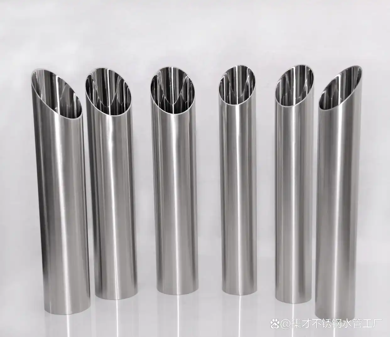
1. from DIN 11850 to EN 10357
In the execution of high-purity industrial process systems, the integration of structural components that eliminate micro-bacterial accumulation pathways is mandatory. For decades, the German industrial standard DIN 11850 served as the dominant engineering framework across continental Europe, defining the technical delivery conditions, spatial tolerances, and geometric dimensions for seamless and welded stainless steel tubes utilized within the food, dairy, chemical, and pharmaceutical processing installations.
To eliminate regional trade barriers and unify the scattered country-specific sanitary manufacturing standards into a common European regulatory framework, the European Committee for Standardization officially enacted EN 10357 in the beginning of 2014. This European Norm successfully harmonized the technical prerequisites for hygienic piping across all member states of the European Union, establishing a standardized baseline for fluid-handling architecture.
Strategic Engineering Note: Although EN 10357 serves as the formal legal successor to DIN 11850, structural legacy systems and current procurement specifications frequently refer to DIN dimensions. Consequently, modern manufacturing lines must operate in complete alignment with both standards, maintaining dimensional sub-classes to accommodate regional engineering protocols.
Within hygienic layout engineering, a sharp distinction must be drawn between pipes intended for general sanitary processes (food and beverage) and those designed for strict aseptic, sterile applications (biotech and pharmaceutical). While DIN 11850 and EN 10357 focus primarily on the sanitary tube parameters, the matching fittings, unions, and component matrices are governed by separate standard layers.
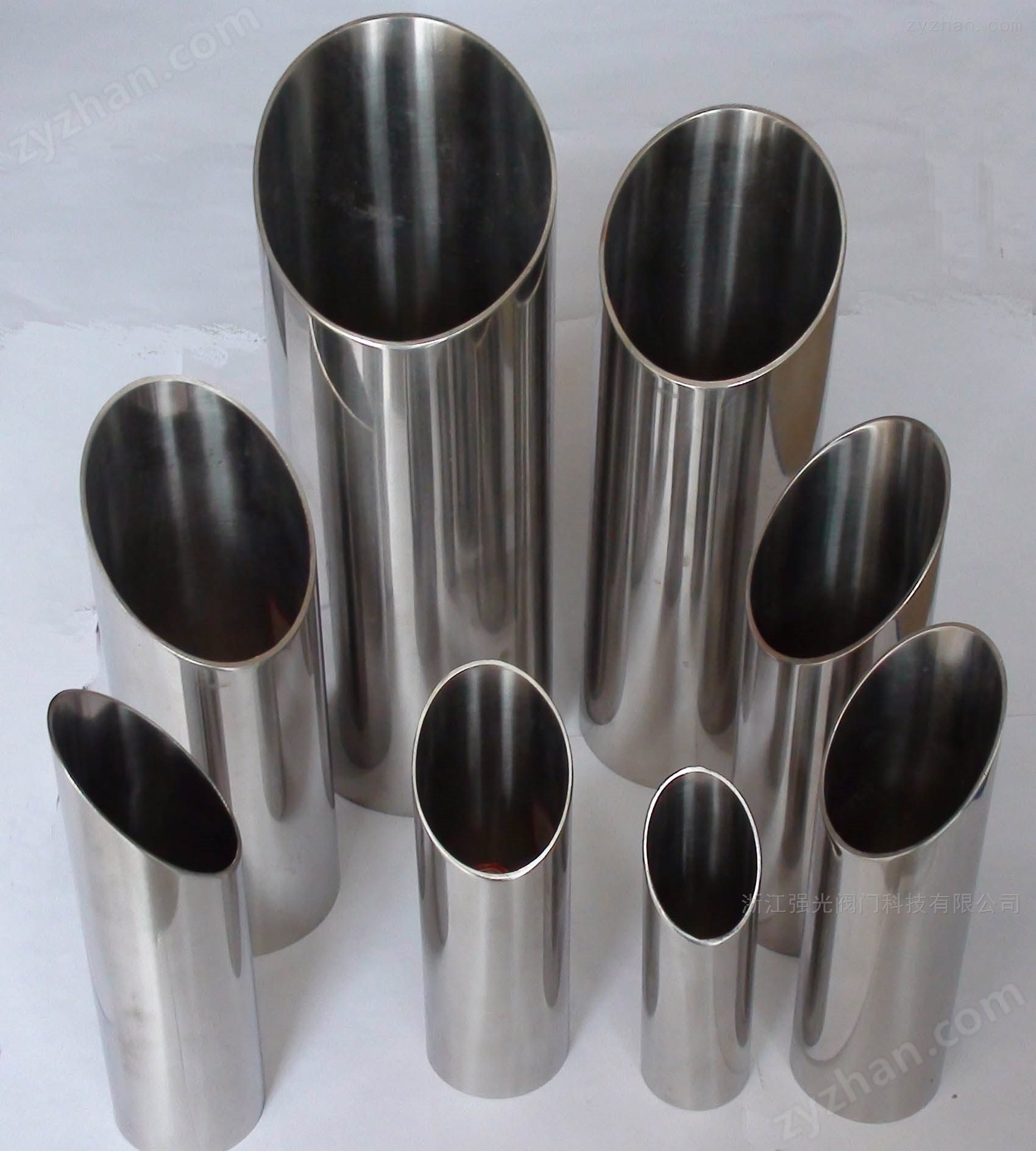
Table 1: European Cross-Reference Matrix for Tubes, Fittings, and Aseptic Classifications
| Application Category | Tube Dimensions & Specs | Fittings & Connections | Target Industry Segments |
|---|---|---|---|
| Standard Sanitary / Hygienic | DIN 11850 (Legacy) | DIN 11851 (Screwed) DIN 11852 (Welding) DIN 11853 (Hygienic Unions) |
Dairy Processing, Breweries, Beverage, Fluid Food Transport, Cosmetics |
| EN 10357 (Current Norm) | |||
| High-Purity Aseptic & Sterile | DIN 11866 | DIN 11864 (Aseptic Unions) DIN 11865 (Aseptic Fittings) |
Biotech, Active Pharmaceutical Ingredients (API), Genetech, Semiconductor Mfg |
2. Metric Geometry, Structural Sub-Classes, and Multi-Standard Harmonization
To manage the various physical dimensions utilized across separate global industrial ecosystems, EN 10357 structures its scope into highly distinct dimensional sub-classes. These designations allow engineering teams to quickly cross-reference whether a production batch follows traditional European metric standards, American high-purity bioprocessing conventions, or international size indexes.
- EN 10357-A (Series A): Follows the legacy dimensions originally dictated by DIN 11850. This is the primary metric framework used for European automated dairy and brewery plants.
- EN 10357-C (Series C): Calibrated to fit the outside diameters and wall thicknesses dictated by American ASME BPE (Bioprocess Equipment) sizing metrics, optimizing lines for cross-continental modular skid assembly.
- EN 10357-D (Series D): Formulated in direct alignment with international ISO 2037 dimensions, serving as the core standard for systems using alternative global component supply chains.
A minor structural deviation between legacy DIN 11850 specifications and the unified EN 10357 lies in the formal documentation of dimensional boundaries for exceptionally large piping runs. Specifically, EN 10357 introduces precise manufacturing tolerance limits for $254\text{ mm}$ outside diameter tubes (DN 250), an outer dimension envelope that lacked a complete, explicit structural specification in the historic German standard text.
Table 2: Dimensional Comparison & Structural Deviations
| Evaluation Parameter | DIN 11850 Specification | EN 10357 Specification |
|---|---|---|
| Sizing Reference Base | Exclusively Metric Nominal Diameter (DN) linked directly to fixed millimeter sizes. | Tri-split framework encompassing Metric (Series A), ASME BPE (Series C), and ISO 2037 (Series D). |
| Large Diameter Envelope ($254\text{ mm}$) | Not explicitly specified / left to individual mill agreement. | Formally standardized with structural tolerance limits defined at $\pm 0.4\text{ mm}$. |
| Surface Finish Nomenclature | Employs direct execution codes: CC, CD, BC, BD. | Combines structural class and execution codes: Class 1 (CL1) or Class 2 (CL2) + CC/CD/BC/BD. |
| Internal Pressure Criteria | Formally tabulates maximum bar allowances at $20^\circ\text{C}$ and $150^\circ\text{C}$. | Omitted from the official standard text (defers to external pressure vessel norms like EN 13480). |
| Straightness Constraint Limit | Identical across both codes: $0.0015 \times \text{Length}$, with a maximum deflection cap of $2\text{ mm}$ per single linear meter. |
3. Metallurgical Characterization & Chemical Composition Thresholds
The mechanical performance and corrosion resistance of sanitary systems depend heavily on precise steel alloying configurations. Materials under DIN 11850 and EN 10357 must be sourced from premium-grade austenitic stainless steel variants synthesized according to EN 10088-2 criteria. The primary alloys utilized are 1.4301 (AISI 304), 1.4307 (AISI 304L), and 1.4404 (AISI 316L).
To mitigate intergranular corrosion risks within heated fluid zones or adjacent to high-temperature orbital weld points, low-carbon variants ($C \le 0.035\%$) are explicitly specified for 1.4307 and 1.4404 arrays. Furthermore, the inclusion of molybdenum ($2.0\% – 3.0\%$) within the 1.4404 formulation guarantees critical resistance against localized pitting and crevice corrosion when handling acidic process streams, cleaning solutions, or high-salinity media.
Table 3: Highly Precise Chemical Composition Limits (Element % by Mass)
| EN Alloy Code | AISI Equiv. | Carbon (C) | Chromium (Cr) | Nickel (Ni) | Molybdenum (Mo) | Manganese (Mn) | Silicon (Si) | Phosphorus (P) | Sulfur (S) |
|---|---|---|---|---|---|---|---|---|---|
| 1.4301 | 304 | ≤ 0.07 | 17.5 – 19.5 | 8.0 – 10.5 | — | ≤ 2.00 | ≤ 1.00 | ≤ 0.045 | ≤ 0.015 |
| 1.4307 | 304L | ≤ 0.030 | 17.5 – 19.5 | 8.0 – 10.5 | — | ≤ 2.00 | ≤ 1.00 | ≤ 0.045 | ≤ 0.015 |
| 1.4404 | 316L | ≤ 0.030 | 16.5 – 18.5 | 10.0 – 13.0 | 2.00 – 2.50 | ≤ 2.00 | ≤ 1.00 | ≤ 0.045 | ≤ 0.015 |
4. Tensile Properties & Mechanical Performance Boundaries
Hygienic pipes must possess a robust balance of high structural tensile limits and outstanding material ductility. This profile allows lines to safely absorb thermal shocks from sequential cleaning processes without cracking or experiencing structural failure.
Mechanical verification, governed by testing parameters outlined in ASME SA270 and EN 10217-7, requires that all structural components undergo a controlled solution annealing thermal protocol. Heated between $1040^\circ\text{C}$ and $1100^\circ\text{C}$ followed by rapid water or air quenching, the microstructure converts into a continuous, non-magnetic austenitic matrix that delivers predictable elongation values.
Table 4: Certified Mechanical Properties & Solution Annealing Conditions
| Material Specification | Min. Yield Strength ($R_{p0.2}$, MPa) |
Tensile Strength ($R_m$, MPa) |
Min. Elongation ($A_5$, %) |
Solution Annealing Temperature ($^\circ\text{C}$) |
|---|---|---|---|---|
| EN 1.4301 / AISI 304 | 205 | 515 – 720 | 35% | 1040 – 1100 |
| EN 1.4307 / AISI 304L | 170 | 485 – 670 | 35% | 1040 – 1100 |
| EN 1.4401 / AISI 316 | 205 | 515 – 720 | 35% | 1040 – 1100 |
| EN 1.4404 / AISI 316L | 170 | 485 – 670 | 35% | 1040 – 1100 |
5. Dimensional Matrix Group A: Light Wall Thickness Profiles ($1.0\text{ mm}$)
Light wall thickness profiles are optimized for low-pressure fluid distribution or ambient-temperature gravity feed lines where reducing system weight is critical. These configurations are frequently integrated into high-volume product storage areas, distribution bypass networks, and secondary venting applications within automated dairy plants.
Table 5: Group A (Light Wall) – Nominal Sizing & Exact Mass Constants
| Nominal Index (DN) | Tube OD ($d_e$, mm) | OD Tolerance (mm) | Wall Thickness ($s$, mm) | WT Tolerance | End Cut Allowance | Theoretical Mass ($M$, kg/m) |
|---|---|---|---|---|---|---|
| DN 10 | 12.0 | ± 0.12 | 1.0 | ± 10% | +3.0 mm / -0.0 | 0.273 |
| DN 15 | 18.0 | ± 0.12 | 1.0 | ± 10% | +3.0 mm / -0.0 | 0.423 |
| DN 20 | 22.0 | ± 0.12 | 1.0 | ± 10% | +3.0 mm / -0.0 | 0.523 |
| DN 25 | 28.0 | ± 0.12 | 1.0 | ± 10% | +3.0 mm / -0.0 | 0.672 |
| DN 32 | 34.0 | ± 0.12 | 1.0 | ± 10% | +3.0 mm / -0.0 | 0.821 |
| DN 40 | 40.0 | ± 0.12 | 1.0 | ± 10% | +3.0 mm / -0.0 | 0.971 |
| DN 50 | 52.0 | ± 0.20 | 1.0 | ± 10% | +3.0 mm / -0.0 | 1.271 |
6. Dimensional Matrix Group B: Standard Wall Thickness Profiles ($1.5\text{ mm} – 2.0\text{ mm}$)
The Group B intermediate profile configuration balances high structural strength with lightweight efficiency. This cross-section handles standard municipal, pharmaceutical, and chemical plant operating pressures, making it the primary dimensional format for water treatment systems, product conveyance lines, and general raw product intake architecture.
Table 6: Group B (Standard Wall) – Complete Metric Sizing and Mass Indexes
| Nominal Index (DN) | Tube OD ($d_e$, mm) | OD Tolerance (mm) | Wall Thickness ($s$, mm) | WT Tolerance | Linear Length Scope (m) | Theoretical Mass ($M$, kg/m) |
|---|---|---|---|---|---|---|
| DN 10 | 13.0 | ± 0.30 | 1.5 | ± 10% | 6.00 | 0.431 |
| DN 15 | 19.0 | ± 0.30 | 1.5 | ± 10% | 6.00 | 0.655 |
| DN 20 | 23.0 | ± 0.30 | 1.5 | ± 10% | 6.00 | 0.805 |
| DN 25 | 29.0 | ± 0.30 | 1.5 | ± 10% | 6.00 | 1.030 |
| DN 32 | 35.0 | ± 0.30 | 1.5 | ± 10% | 6.00 | 1.255 |
| DN 40 | 41.0 | ± 0.30 | 1.5 | ± 10% | 6.00 | 1.480 |
| DN 50 | 53.0 | ± 0.30 | 1.5 | ± 10% | 6.00 | 1.931 |
| DN 65 | 70.0 | ± 0.30 | 2.0 | ± 10% | 6.00 | 3.400 |
| DN 80 | 85.0 | ± 0.30 | 2.0 | ± 10% | 6.00 | 4.150 |
| DN 100 | 104.0 | ± 0.30 | 2.0 | ± 10% | 6.00 | 5.101 |
| DN 125 | 129.0 | ± 0.40 | 2.0 | ± 10% | 6.00 | 6.350 |
| DN 150 | 154.0 | ± 0.40 | 2.0 | ± 10% | 6.00 | 7.601 |
| DN 200 | 204.0 | ± 0.40 | 2.0 | ± 10% | 6.00 | 10.100 |
| DN 250 | 254.0 | ± 0.40 | 2.0 | ± 10% | 6.00 | 12.601 |
7. Dimensional Matrix Group C: Heavy Wall Thickness Profiles ($2.0\text{ mm} – 2.5\text{ mm}$)
For high-temperature processing zones, sterile steam loops, or lines carrying highly corrosive chemical compounds, relying on light structures presents operational risks. Group C thick-walled configurations deliver the burst-pressure safety factor necessary for multi-stage pasteurization arrays, high-velocity evaporation lines, and modern chemical processing facilities.
Table 7: Group C (Heavy Wall) – Geometric Parameters & Mass Values
| Nominal Index (DN) | Tube OD ($d_e$, mm) | OD Tolerance (mm) | Wall Thickness ($s$, mm) | WT Tolerance | End Squareness Constraint | Theoretical Mass ($M$, kg/m) |
|---|---|---|---|---|---|---|
| DN 10 | 14.0 | ± 0.30 | 2.0 | ± 10% | ≤ 0.5% of OD | 0.601 |
| DN 15 | 20.0 | ± 0.30 | 2.0 | ± 10% | ≤ 0.5% of OD | 0.901 |
| DN 20 | 24.0 | ± 0.30 | 2.0 | ± 10% | ≤ 0.5% of OD | 1.102 |
| DN 25 | 30.0 | ± 0.30 | 2.0 | ± 10% | ≤ 0.5% of OD | 1.402 |
| DN 32 | 36.0 | ± 0.30 | 2.0 | ± 10% | ≤ 0.5% of OD | 1.703 |
| DN 40 | 42.0 | ± 0.30 | 2.0 | ± 10% | ≤ 0.5% of OD | 2.003 |
| DN 50 | 54.0 | ± 0.30 | 2.0 | ± 10% | ≤ 0.5% of OD | 2.604 |
8. Hydrostatic Internal Pressure Thresholds & Structural Calculations
Unlike legacy German rules, EN 10357 does not explicitly define internal pressure limits within its main text, deferring instead to regional pressure vessel design rules. However, to guarantee structural safety factors, engineering teams rely on the core formulas recorded in DIN 11850 and AD-Merkblatt B1/B9.
The baseline structural capacity calculations evaluate a cylindrical shell segment without cutouts ($P_{max}$), assuming a 100% efficient longitudinal weld joint. Because austenitic steel softens at higher temperatures, pressure ratings must be reduced by up to 40% when operating under Sterilization-in-Place (SIP) conditions at $150^\circ\text{C}$.
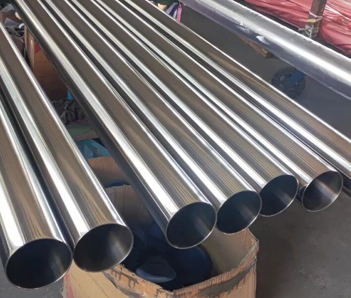
Table 8: Maximum Working Pressure Bounds (Bar) for 1.4301 Welded Configurations
| DN Sizing Code | 10 | 15 | 20 | 25 | 32 | 40 | 50 | 65 | 80 | 100 | 125 | 150 | 200 |
|---|---|---|---|---|---|---|---|---|---|---|---|---|---|
| Limit at $20^\circ\text{C}$ (Bar) | 355 | 242 | 200 | 159 | 131 | 112 | 87 | 87 | 72 | 59 | 47 | 39 | 30 |
| Limit at $150^\circ\text{C}$ (Bar) | 219 | 150 | 124 | 98 | 81 | 69 | 53 | 54 | 44 | 36 | 29 | 24 | 18 |
9. Internal Surface Finish Topography & Micro-Roughness Constants
Maintaining strict control over internal surface topography is essential for preventing microbial growth or bio-film attachment. Both standards enforce strict limitations on the maximum allowable internal Roughness Average ($R_a$).
To ensure repeatable cleanability during Clean-in-Place (CIP) processes, the internal surface must maintain an $R_a \le 0.8\ \mu\text{m}$. For high-purity pharmaceutical sectors, finishing requirements are further restricted to $R_a \le 0.4\ \mu\text{m}$ or better, typically achieved through specialized mechanical abrading followed by an electropolishing treatment layer.
Table 9: Surface Roughness Designations, Treatment Protocols & Target Limits
| EN Code | Legacy Code | Process State & Thermal Treatment | Internal Body ($R_a\ \mu\text{m}$) | Welded Seam ($R_a\ \mu\text{m}$) | External Surface ($R_a\ \mu\text{m}$) |
|---|---|---|---|---|---|
| CL1 BC | BC | Bright Annealed, Mechanically Polished | ≤ 0.80 | ≤ 1.60 | Pickled (≤ 1.60) |
| CL1 BD | BD | Bright Annealed, Ground Outside | ≤ 0.80 | ≤ 1.60 | ≤ 1.00 |
| CL1 CC | CC | Not Annealed, Pickled Clean | ≤ 0.80 | ≤ 1.60 | Pickled (≤ 1.60) |
| CL1 CD | CD | Not Annealed, Externally Ground | ≤ 0.80 | ≤ 1.60 | ≤ 1.00 |
| Tri-Clover | 3A Spec | High-Purity Electropolished Variant | ≤ 0.38 | ≤ 0.38 | ≤ 0.80 |
10. Alternative Surface Topography & Grit Polishing Conversion
To assist procurement divisions evaluating international supplies, converting mechanical grit designations to precise metrology values is essential. While grit size refers to the abrasive medium’s particle density, the formal certification criteria rely on actual roughness measurements ($R_a$) to verify sanitary compliance.
Table 10: Grit Abrasive Processing to Roughness Micron / Micro-inch Conversion
| Abrasive Finishing Format | Roughness ($R_a$, Micro-inches) | Roughness ($R_a$, Microns) | ISO 4287 Designation | Electropolishing Polish Finish Post-Layer |
|---|---|---|---|---|
| 150 Grit Finish | 30 – 35 | 0.75 – 0.875 | N6 | Not Applicable |
| 150 Grit + Electropolish | 12 – 20 | 0.30 – 0.50 | N5 | Fully Applied |
| 180 Grit Finish | 20 – 25 | 0.50 – 0.625 | N5 | Not Applicable |
| 180 Grit + Electropolish | 10 – 16 | 0.25 – 0.40 | N4 | Fully Applied |
| 240 Grit Finish | 15 – 20 | 0.375 – 0.50 | N5 | Not Applicable |
| 240 Grit + Electropolish | 8 – 12 | 0.20 – 0.30 | N4 | Fully Applied |
| 320 Grit Finish | 8 – 12 | 0.20 – 0.30 | N4 | Not Applicable |
| 320 Grit + Electropolish | 6 – 12 | 0.15 – 0.30 | Ultra-Clean | Fully Applied |
11. Quality Control Protocols, Testing Methodologies & Metrology Standards
Verifying compliance with EN 10357 and DIN 11850 requires rigorous non-destructive and destructive testing. Mechanical properties, chemical matrices, and surface parameters must be validated per EN 10217-7 Test Category 1 (TC1) rules, or Test Category 2 (TC2) protocols under AD-2000-Merkblatt W2 conditions.
Roughness tests are executed following DIN EN ISO 4287 and DIN EN ISO 4288 protocols. Inspectors measure surface parameters at the end of the tube, exactly $5\text{ mm}$ from the edge, evaluating a minimum of 1 in 20 tubes from every production heat. For externally ground profiles (Types CD and BD), ratio measurements are conducted at least $100\text{ mm}$ from the tube end to rule out edge-polishing distortion.
Table 11: Mandated QA Inspection Testing Threshold Matrix
| Testing Target | Reference Norm | Procedural Method / Criteria | Minimum Frequency |
|---|---|---|---|
| Weld Seam Integrity | EN 10217-7 / EN ISO 10893-1 | Continuous non-destructive Eddy Current testing or Hydrostatic verification loops. | 100% of Batch |
| Surface Roughness ($R_a$) | DIN EN ISO 4287 / 4288 | Stylus profilometer measurement taken $5\text{ mm}$ from the tube end across both the weld zone and inner parent metal. | 5% of Lengths (1:20) |
| Dimensional Compliance | EN 10357 / DIN 11850 | Micrometer outside diameter confirmation and laser wall-thickness wall scans. | 100% of Batch |
| Weld Deformability | EN ISO 8492 / 8493 | Destructive ring flattening and drift expansion testing to confirm cold-forming flexibility. | Once per heat bundle |
12. System Traceability, Marking Standards & Mill Certifications
Complete materials traceability is a foundation of modern sanitary engineering quality assurance. In high-purity processing sectors, full asset tracking ensures that any raw material defect can be isolated rapidly, mitigating risk across the production chain.
To maintain documentation integrity, all pipes must be clearly stamped with the manufacturer’s mark, standard codes, dimensions, surface specification, and the specific material heat number. Furthermore, deliveries must include a certified EN 10204 3.1 Material Test Report (MTR), validating the exact chemical composition and mechanical properties.
Table 12: Mandated Stamping and Documentation Verification
| Required Marking Parameter | Stamping Syntax Example | Verification Requirement |
|---|---|---|
| Origin Tracking | MILL-NAME GERMANY | Identifies the manufacturing site and location. |
| Standard Compliance | EN 10357-A / DIN 11850 | Confirms the dimensional sub-class framework. |
| Dimensional Profile | DN50 $53.0 \times 1.5\text{ mm}$ | Confirms outside diameter and wall thickness. |
| Surface Execution Code | CL1 BD | Validates the roughness class criteria. |
| Traceability Identity | HEAT NO. H2026X57 | Links back to the melt shop batch profile. |
13. Elastomeric Sealing Compatibility & Chemical Resistance Profiles
Building a reliable hygienic process system requires selecting compatible elastomeric gaskets to seal joint couplings, union nuts, and Tri-Clamp ferrules. An unsuited elastomeric compounds can degrade rapidly when exposed to aggressive product chemistry or harsh Clean-in-Place (CIP) solutions.
For instance, standard Nitrile Rubber (NBR) displays limited resistance when subjected to high-concentration hot lye cycles or active steam lines. Conversely, premium polymers like Ethylene Propylene Diene Monomer (EPDM) or Polytetrafluoroethylene (PTFE) maintain material integrity under intense sterilization environments, preventing seal degradation and process fluid contamination.
Table 13: Comprehensive Product and Chemical Resistance Ratings for Elastomeric Compounds
| Media Type or Process Stream | NBR | HNBR | EPDM | Silicone (Q) | FPM (Viton) | PTFE (Teflon) |
|---|---|---|---|---|---|---|
| Standard Dairy (Milk, Cream) | 3 | 3-4 | 3-4 | 3-4 | — | 4 (High) |
| Cultured Sour Milk Varieties | 3 | 3-4 | 3-4 | 3-4 | — | 4 (High) |
| Brewery Streams (Beer, Hops) | 3 | 3-4 | 3-4 | 1-2 | 2-3 | 4 (High) |
| Wine Processing and Yeasts | 3 | 3-4 | 4 | 4 | 2-3 | 4 (High) |
| Animal & Vegetable Fats (to $100^\circ\text{C}$) | 3 | 4 | 1-2 | 3 | 4 | 4 (High) |
| Hot Process Water / Steam (to $130^\circ\text{C}$) | 1 (Fail) | 4 | 4 | 2 | — | 4 (High) |
| Non-Oxidizing Acids (to $80^\circ\text{C}$) | 1-2 | 2 | 3 | 1-2 | 2 | 3-4 |
| Weak Alkaline Lye Blends (to $100^\circ\text{C}$) | 2 | 3-4 | 4 | 2 | 2 | 4 (High) |
| Concentrated CIP Caustic Cleaners | 1 (Fail) | 2-3 | 3 | 1 | 1 | 4 (High) |
* Note: Performance indexing values are compiled following global ISO R 1629 rubber classification rules. (Key: 4 = High Suitability; 3 = Normal Suitability; 2 = Limited Suitability; 1 = Unsuitable).
14. Inner Geometric Area & Volumetric Displacement Matrices
Calculating precise fluid displacement requires analyzing the exact internal diameter ($d_i$) of the pipe run. Because wall thickness parameters vary across different structural series, the inner cross-sectional area changes significantly between Group A and Group C classes.
Hygienic process design requires minimizing flow resistance and maintaining optimal pressure conditions. The table below outlines the true internal cross-sectional areas and relative fluid capacities across key standard nominal diameter segments.
Table 14: True Internal Cross-Sectional Area and Capacity Index Matrix
| Sizing Index (DN) | Standard OD (mm) | Wall Class (mm) | True ID ($d_i$, mm) | Internal Area ($\text{cm}^2$) | Unit Fluid Vol. (L/m) |
|---|---|---|---|---|---|
| DN 25 | 29.0 | 1.5 | 26.0 | 5.31 | 0.531 |
| 2.0 | 25.0 | 4.91 | 0.491 | ||
| DN 50 | 53.0 | 1.5 | 50.0 | 19.63 | 1.963 |
| 2.0 | 49.0 | 18.86 | 1.886 | ||
| DN 100 | 104.0 | 2.0 | 100.0 | 78.54 | 7.854 |
| 2.5 | 99.0 | 76.97 | 7.697 |
15. Welding Specifications & Heat-Affected Zone (HAZ) Safety
To connect hygienic lines while keeping the flow path smooth and seamless, automated orbital TIG welding is widely utilized. Achieving a high-quality joint requires managing heat input to prevent chromium carbide precipitation along the grain boundaries.
Proper oxygen management inside the pipe during welding is critical. Using high-purity argon backing gas ($>99.995\%$) maintains low oxygen levels within the purge chamber, eliminating oxide discoloration that can compromise the passive surface layer and lead to corrosion.
Table 15: Orbital TIG Welding Parameters & Purge Shielding Protocols
| Welding Parameter | Operational Target & Controlled Settings | Target Value Metric |
|---|---|---|
| Purge Oxygen Limit | Maximum allowable oxygen concentration inside the internal purge path before starting the arc sequence. Prevents weld root oxidation. | ≤ 25 ppm |
| Shielding Gas Purity | Torch and backing gas composition. Must be completely free of hydrocarbons and moisture to avoid weld porosity. | 99.995% Argon min. |
| Linear Heat Input | Energy delivered per unit length during welding. Controlled to maintain microstructural balance and prevent grain growth. | 0.5 – 1.2 kJ/mm |
| Misalignment Limit | Maximum allowable step height between matching pipe walls at the joint. Prevents internal crevices that can trap process fluid. | ≤ 10% of wall thickness |
16. On-Site Logistics, Storage Protocols & Installation Alignment Criteria
Preserving the precision tolerances and surface quality of hygienic pipes requires careful material handling during shipping and on-site storage. To avoid galvanic contamination, stainless steel profiles must be stored separately from carbon steel components.
Pipes should be supported by wood dunnage strips or padded racks to prevent point-load deformation. Additionally, high-purity lines must be installed with a consistent slope gradient to guarantee full self-draining performance, eliminating fluid entrapment zones that could compromise system hygiene.
Table 16: Storage and On-Site Handling Requirements
| Handling Phase | Mandated Procedure & Protection Criteria | Target Limit Metric |
|---|---|---|
| Warehouse Storage | Store indoors on padded racks, isolated from carbon steel. Keep protective plastic end caps firmly in place to exclude airborne dust. | 100% dry environment |
| Lifting Logistics | Utilize clean nylon slings or polymer-coated hooks during transit. Never use bare steel chains or forklifts directly on stainless pipe bundles. | Zero surface scoring |
| Drainage Alignment | Horizontal runs must be pitched downward toward drain valves to ensure complete system evacuation during cleaning cycles. | Min. slope 1:100 (1%) |
17. Non-Destructive Testing (NDT) & Metallurgical Integrity Verification
To secure compliance with the strict standards governing the European food, dairy, and pharmaceutical manufacturing matrix, every production run of EN 10357 / DIN 11850 tubes must pass a rigorous matrix of internal non-destructive tests. These procedures guarantee structural endurance under cyclic thermal stress and eliminate risk of pinhole leakage at high process pressures.
The primary methodology deployed inline is 100% automated eddy current testing in full compliance with EN ISO 10893-1 or EN ISO 10893-2. This electromagnetic testing system rapidly evaluates the continuity of both the parent metal matrix and the autogenous fusion weld line, isolating microscopic longitudinal wall fissures, slag inclusions, or internal gas pockets that are invisible to the naked eye.
Table 17: Mandatory Quality Inspection Matrix and Acceptance Benchmarks
| Testing Category | Testing Methodology & Reference Regulation | Mandated Acceptance Standard |
|---|---|---|
| Eddy Current Flaw Detection | Continuous inline electromagnetic evaluation targeting parent strip and seam weld zone integrity in accordance with EN ISO 10893-2. | Zero signal deviation (No cracks) |
| Mechanical Weld Flattening | Destructive evaluation via severe compressive deformation of sample coupons at 90° orientation relative to the weld plane per EN ISO 8492. | No micro-fissures or weld splits |
| Dimensional Laser Audit | Continuous high-speed 360-degree non-contact laser telemetry to confirm nominal outside diameter uniformity and cross-sectional roundness. | Strictly inside EN 10357 envelope |
18. Post-Manufacturing Chemical Passivation & Surface Chemistry Optimization
To achieve maximum localized pitting resistance equivalent (PREN) metrics within process networks, finished austenitic and duplex hygienic steel tubes undergo precise chemical immersion passivation. This metallurgical processing removes any trace elemental free iron embedded on the inner tube wall from raw mechanical drawing and polishing media.
By contacting the ultra-smooth surfaces with targeted formulations of either nitric acid ($HNO_3$) or organic citric acid, the surface chromium concentration rises artificially relative to iron. This process accelerates the generation of a continuous, cohesive chromium oxide ($Cr_2O_3$) passive barrier layer. This molecular barrier effectively blocks ionic penetration from aggressive CIP cleaning media containing hot caustic soda or acid sanitizers.
Table 18: Standard Industrial Chemical Passivation Parameters
| Chemical Formulation | Volumetric Solution Temp. | Immersion Duration | Target Pass Passive Ratio |
|---|---|---|---|
| Nitric Acid (20% – 25% $HNO_3$) | 45°C – 55°C | 20 – 30 Minutes | Cr:Fe Ratio ≥ 1.5 via XPS |
| Citric Acid (4% – 10% Chelation) | 50°C – 65°C | 30 – 45 Minutes | Cr:Fe Ratio ≥ 1.2 via XPS |
19. Regulatory Traceability & Material Certification Standards
In sterile processing environments, material origin and structural transparency are non-negotiable legal imperatives. All piping materials built to EN 10357 must maintain unbroken structural tracking from the primary melting stage down through final finishing operations. Each lot is cross-referenced to specific mill heat numbers via indelible laser marking along the exterior length of the pipe profile.
To secure structural sign-off from system auditors, delivery paperwork must feature an official EN 10204 Type 3.1 inspection certificate. This document tracks ladle sample chemical configurations, accurate mechanical breakdown metrics (including yield strengths $R_{p0.2}$, ultimate tensile limits $R_m$, and percent elongation $A$), as well as documented inner wall micrometer roughness ($R_a$) parameters.
Table 19: Regulatory Traceability Framework Standards
| Regulatory Mechanism | Verification Scope & Tracking Attributes | Compliance Level |
|---|---|---|
| EN 10204 Type 3.1 Certificate | Mandatory validation listing real physical mill mechanical results and chemical values from independent testing supervisors. | Fully Traceable Heat Tracked |
| EC No 1935/2004 Alignment | Confirms the alloy formulation will not leach hazardous heavy elements into liquid food flow streams during operational contact. | Food-Contact Approved |
| Continuous Laser Stenciling | Permanent structural surface marking stating standard reference codes, accurate dimensions, steel grade name, and primary heat code. | 100% In-field Identification |
20. CIP/SIP Protocol Compatibility & Preventive Maintenance Chemistries
Maintaining the ultra-low internal surface roughness ($R_a \le 0.40\,\mu\text{m} – 0.80\,\mu\text{m}$) of EN 10357 hygienic pipelines over multi-year production campaigns requires strict adherence to standardized Clean-In-Place (CIP) and Steam-In-Place (SIP) thermal regimes. Improper chemical exposure or inadequate fluid velocities can lead to localized “rouging”—the formation of micro-scale iron oxide or hydroxide films that degrade the passive chromium oxide layer.
To thoroughly clear organic residue and neutralize biological matrices without inducing pitting corrosion, processing lines must encounter an alternating cycle of formulated alkaline detergents and acidic neutralizing rinses. Furthermore, SIP operations utilizing saturated steam up to 134°C demand careful monitoring of thermal expansion variables ($16.5 \times 10^{-6}/\text{K}$ for 1.4404 steel) to eliminate mechanical stress along internal orbital weld seams.
Table 20: Standard CIP/SIP Operational Cycle Thresholds
| Operational Phase | Chemical Composition / Medium | Thermal Range | Target Kinetic Threshold |
|---|---|---|---|
| Alkaline CIP Wash | Sodium Hydroxide ($NaOH$) 1.0% – 2.0% wt. | 75°C – 85°C | Min. Velocity: 1.5 m/s |
| Acid CIP Rinse | Nitric Acid ($HNO_3$) 0.5% – 1.0% wt. | 50°C – 60°C | Passivation Maintenance |
| SIP Thermal Cycle | Saturated Clean Steam (Dryness > 95%) | 121°C – 134°C | Exposure: 20 – 30 mins |
21. Fluid Dynamics & Boundary Layer Mechanical Considerations
From an engineering perspective, the interior dimension matrices defined by EN 10357 (Series A through D) are optimized mathematically to control turbulent flow profiles and boundary layer shear stress. When high-viscosity food mixtures or shear-sensitive biological materials pass through a hygienic network, the smooth wall design minimizes pressure drops and prevents internal pocket separation.
Maintaining a fully developed turbulent flow regime (Reynolds Number $Re > 4000$) during CIP execution is essential to generate the necessary wall shear stress to mechanically dislodge biofilm. Because the cross-sectional geometry of Series A matches metric pumps and fittings exactly, process plants can minimize the use of concentric reducers, reducing turbulence-induced cavitation spots that erode underlying passive chromium surfaces.
Table 21: Hydraulic Evaluation Parameters across Nominal Sizes (Series A)
| Nominal Size | Internal Diameter ($D_i$) | Flow Area Cross-Section | Target Volumetric Rate (at 1.5 m/s) |
|---|---|---|---|
| DN25 | 26.0 mm | 530.9 $\text{mm}^2$ | ~ 2.87 $\text{m}^3/\text{h}$ |
| DN40 | 38.0 mm | 1134.1 $\text{mm}^2$ | ~ 6.12 $\text{m}^3/\text{h}$ |
| DN50 | 50.0 mm | 1963.5 $\text{mm}^2$ | ~ 10.60 $\text{m}^3/\text{h}$ |
| DN100 | 100.0 mm | 7854.0 $\text{mm}^2$ | ~ 42.41 $\text{m}^3/\text{h}$ |
The chemical compositions, structural parameters, and dimensional configurations in this directory comply with official European standards. Before finalizing process layouts or piping system engineering calculations, verify individual requirements against the mill-issued EN 10204 3.1 inspection certificate.
You must be logged in to post a comment.