
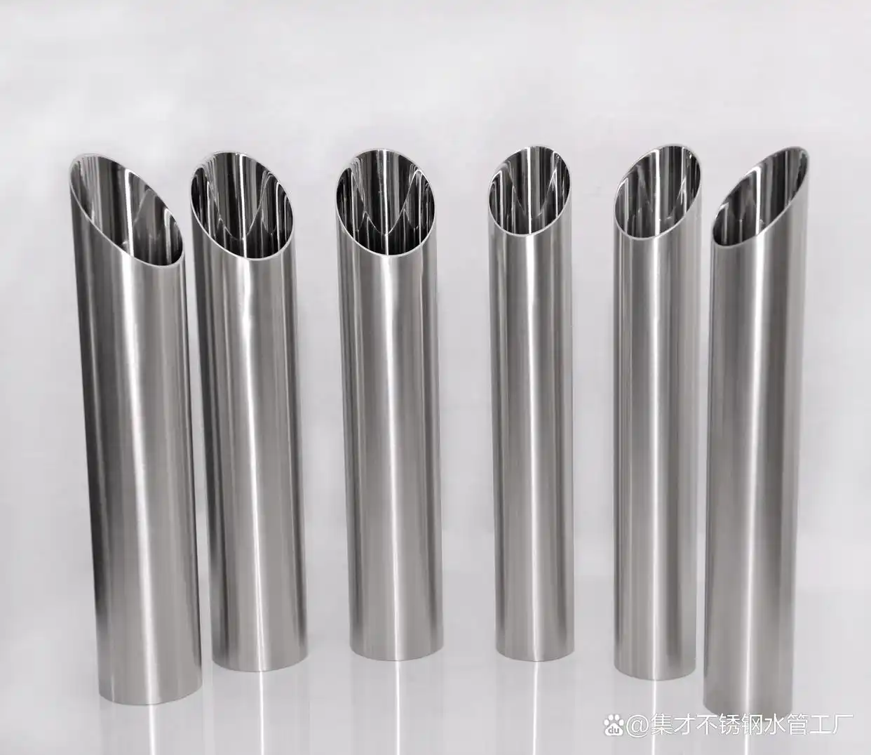
1. DIN'den 11850 iki BİR 10357
Yüksek saflıkta endüstriyel proses sistemlerinin uygulanmasında, Mikro bakteriyel birikim yollarını ortadan kaldıran yapısal bileşenlerin entegrasyonu zorunludur. Onlarca yıldır, Alman endüstri standardı DİN 11850 Kıta Avrupası'nda baskın mühendislik çerçevesi olarak hizmet etti, Teknik teslimat koşullarının tanımlanması, mekansal toleranslar, Gıda sektöründe kullanılan dikişsiz ve kaynaklı paslanmaz çelik boruların geometrik boyutları ve boyutları, Günlük, Kimyasal, ve farmasötik işleme tesisleri.
Bölgesel ticaret engellerini ortadan kaldırmak ve dağınık ülkelere özgü sıhhi üretim standartlarını ortak bir Avrupa düzenleyici çerçevesinde birleştirmek, Avrupa Standardizasyon Komitesi resmi olarak yürürlüğe girdi TR 10357 başında 2014. Bu Avrupa Normu, Avrupa Birliği'nin tüm üye devletlerinde hijyenik boru tesisatına yönelik teknik ön koşulları başarılı bir şekilde uyumlaştırmıştır., Sıvı işleme mimarisi için standartlaştırılmış bir temel oluşturma.
Stratejik Mühendislik Notu: TR olmasına rağmen 10357 DIN'in resmi yasal halefi olarak hizmet vermektedir 11850, yapısal eski sistemler ve mevcut tedarik spesifikasyonları sıklıkla DIN boyutlarına atıfta bulunur. Sonuç olarak, modern üretim hatları her iki standartla da tam uyum içinde çalışmalıdır, bölgesel mühendislik protokollerine uyum sağlamak için boyutsal alt sınıfların sürdürülmesi.
Hijyenik düzen mühendisliği kapsamında, Genel sıhhi işlemlere yönelik borular arasında keskin bir ayrım yapılmalıdır. (Yiyecek ve içecek) ve sıkı aseptik için tasarlanmış olanlar, steril uygulamalar (biyoteknoloji ve ilaç). Dinken 11850 ve TR 10357 öncelikle hijyenik tüp parametrelerine odaklanın, eşleşen bağlantı parçaları, sendikalar, ve bileşen matrisleri ayrı standart katmanlar tarafından yönetilir.
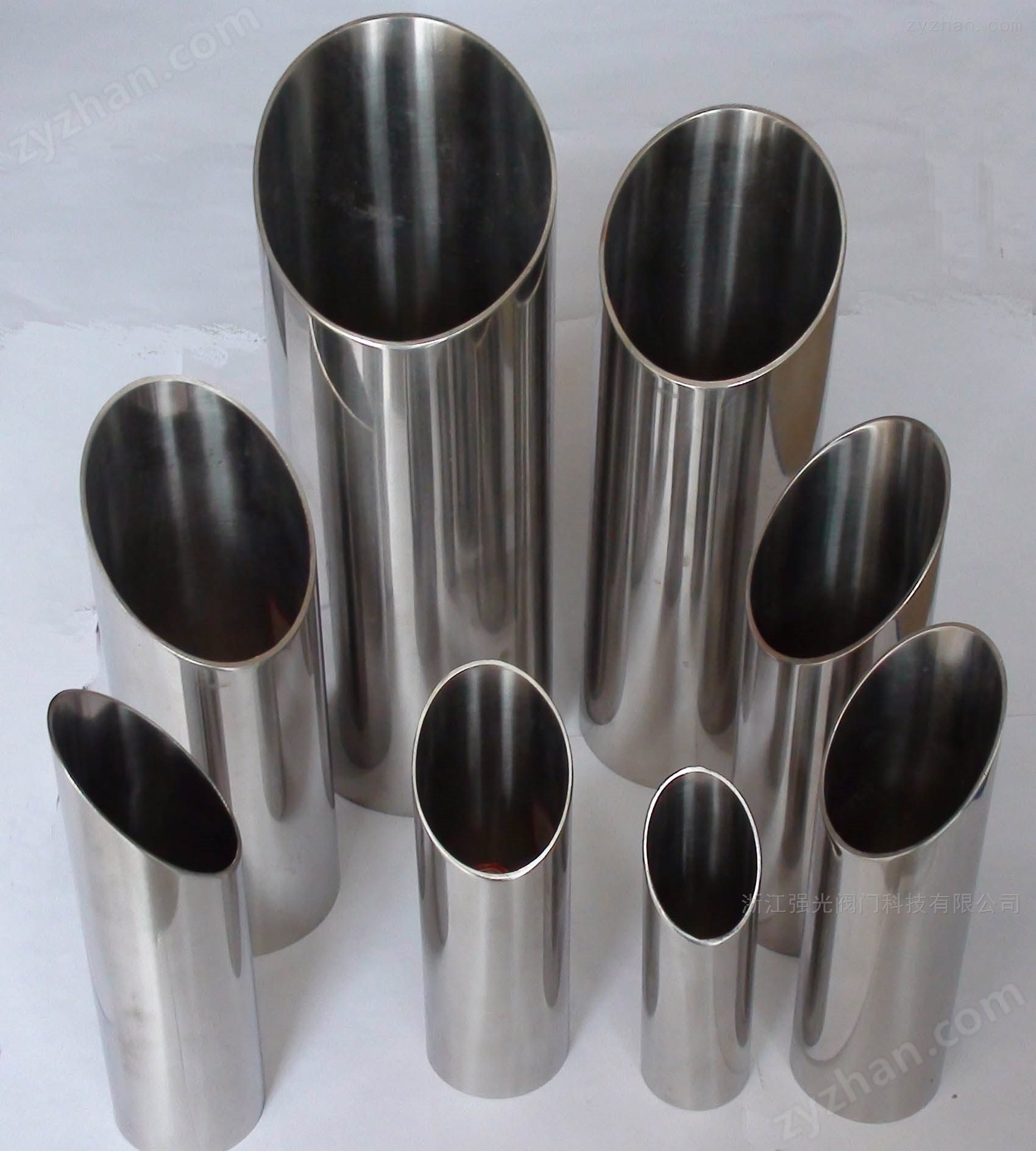
tablo 1: Tüpler için Avrupa Çapraz Referans Matrisi, BAĞLANTI PARÇALARI, ve Aseptik Sınıflandırmalar
| Uygulama Kategorisi | Tüp Boyutları & özellikler | BAĞLANTI PARÇALARI & Bağlantıları | Hedef Endüstri Segmentleri |
|---|---|---|---|
| Standart Hijyen / Hijyenik | DİN 11850 (Miras) | DİN 11851 (Berbat) DİN 11852 (Kaynak) DİN 11853 (Hijyenik Birlikler) |
Süt Ürünleri İşleme, Bira, İçecek, Sıvı Gıda Taşımacılığı, Kozmetik |
| TR 10357 (Mevcut Norm) | |||
| Yüksek Saflıkta Aseptik & Steril | DİN 11866 | DİN 11864 (Aseptik Birleşimler) DİN 11865 (Aseptik Bağlantı Parçaları) |
Biyoteknoloji, Aktif Farmasötik İçerikler (API), Genetech, Yarı İletken Mfg |
2. Metrik Geometri, Yapısal Alt Sınıflar, ve Çok Standartlı Uyumlaştırma
Ayrı küresel endüstriyel ekosistemlerde kullanılan çeşitli fiziksel boyutları yönetmek, TR 10357 kapsamını oldukça farklı boyutlu alt sınıflar halinde yapılandırır. Bu tanımlamalar, mühendislik ekiplerinin bir üretim grubunun geleneksel Avrupa metrik standartlarını takip edip etmediği konusunda hızlı bir şekilde çapraz referans oluşturmasına olanak tanır., Amerikan yüksek saflıkta biyoişleme sözleşmeleri, veya uluslararası boyut indeksleri.
- EN 10357-A (SERİSİ A): Başlangıçta DIN tarafından belirlenen eski boyutları takip eder 11850. Bu, Avrupa otomatik süt ürünleri ve bira fabrikası tesisleri için kullanılan birincil metrik çerçevedir..
- EN 10357-C (C Serisi): Amerikan ASME BPE tarafından belirlenen dış çaplara ve et kalınlıklarına uyacak şekilde kalibre edilmiştir (Biyoproses Ekipmanları) boyutlandırma metrikleri, Kıtalararası modüler kızak montajı için hatları optimize etme.
- EN 10357-D (D Serisi): Uluslararası ISO ile doğrudan uyumlu olarak formüle edilmiştir 2037 Boyutlar, Alternatif küresel bileşen tedarik zincirlerini kullanan sistemler için temel standart görevi görüyor.
Eski DIN ile küçük bir yapısal sapma 11850 teknik özellikler ve birleştirilmiş EN 10357 olağanüstü büyük boru hatları için boyutsal sınırların resmi belgelenmesinde yatmaktadır. özellikle, TR 10357 için kesin üretim tolerans sınırları getiriyor $254\text{ mm}$ dış çaplı borular (DN 250), tam olmayan bir dış boyut zarfı, Tarihi Alman standart metninde açık yapısal spesifikasyon.
tablo 2: Boyutsal Karşılaştırma & Yapısal Sapmalar
| Değerlendirme Parametresi | DİN 11850 Belirtimi | TR 10357 Belirtimi |
|---|---|---|
| Boyutlandırma Referans Tabanı | Özel Metrik Nominal Çap (DN) doğrudan sabit milimetre boyutlarına bağlı. | Metric'i kapsayan üçe bölünmüş çerçeve (SERİSİ A), ASME BPE (C Serisi), ve ISO 2037 (D Serisi). |
| Büyük Çaplı Mektup ($254\text{ mm}$) | Açıkça belirtilmemiş / Bireysel değirmen anlaşmasına bırakıldı. | Tanımlanan yapısal tolerans sınırlarıyla resmi olarak standartlaştırılmıştır. $\pm 0.4\text{ mm}$. |
| Yüzey Cilası Adlandırması | Doğrudan yürütme kodlarını kullanır: CC, CD, M.Ö., BD. | Yapısal sınıf ve yürütme kodlarını birleştirir: Sınıf 1 (CL1) veya Sınıf 2 (CL2) + CC/CD/BC/BD. |
| İç Basınç Kriterleri | Maksimum çubuk ödeneklerini resmi olarak tablolaştırır $20^\circ\text{C}$ ve $150^\circ\text{C}$. | Resmi standart metinden çıkarıldı (EN gibi harici basınçlı kap normlarına uygundur 13480). |
| Doğruluk Kısıtlama Limiti | Her iki kodda da aynı: $0.0015 \times \text{Length}$, maksimum sapma sınırına sahip $2\text{ mm}$ tek doğrusal metre başına. |
3. Metalurjik Karakterizasyon & Kimyasal Bileşim Eşikleri
Sıhhi sistemlerin mekanik performansı ve korozyon direnci büyük ölçüde hassas çelik alaşım konfigürasyonlarına bağlıdır.. DIN kapsamındaki malzemeler 11850 ve TR 10357 EN'ye göre sentezlenmiş birinci sınıf östenitik paslanmaz çelik çeşitlerinden tedarik edilmelidir 10088-2 Kriterler. Kullanılan birincil alaşımlar şunlardır: 1.4301 (AISI 304), 1.4307 (AISI 304L), ve 1.4404 (AISI316L).
Isıtılmış akışkan bölgelerinde veya yüksek sıcaklıktaki yörünge kaynak noktalarının yakınında tanecikler arası korozyon risklerini azaltmak için, düşük karbonlu varyantlar ($C \le 0.035\%$) için açıkça belirtilmiştir 1.4307 ve 1.4404 diziler. Üstelik, molibdenin dahil edilmesi ($2.0\% – 3.0\%$) içinde 1.4404 formülasyon, asidik proses akışlarını işlerken lokal çukurlaşma ve çatlak korozyonuna karşı kritik direnci garanti eder, temizlik çözümleri, veya yüksek tuzluluk ortamı.
tablo 3: Son Derece Hassas Kimyasal Bileşim Sınırları (ELEMAN % kütleye göre)
| TR Alaşım Kodu | AISI Eşdeğeri. | Karbon (C) | Krom (CR) | Nikel (Ni) | Molibden (Mo) | Manganez (MN) | Silikon (Si) | fosfor (P) | Kükürt (S) |
|---|---|---|---|---|---|---|---|---|---|
| 1.4301 | 304 | ≤ 0.07 | 17.5 – 19.5 | 8.0 – 10.5 | - | ≤ 2.00 | ≤ 1.00 | ≤ 0.045 | ≤ 0.015 |
| 1.4307 | 304L | ≤ 0.030 | 17.5 – 19.5 | 8.0 – 10.5 | - | ≤ 2.00 | ≤ 1.00 | ≤ 0.045 | ≤ 0.015 |
| 1.4404 | 316L | ≤ 0.030 | 16.5 – 18.5 | 10.0 – 13.0 | 2.00 – 2.50 | ≤ 2.00 | ≤ 1.00 | ≤ 0.045 | ≤ 0.015 |
4. Çekme Özellikleri & Mekanik Performans Sınırları
Hijyenik borular, yüksek yapısal çekme limitleri ile olağanüstü malzeme sünekliği arasında sağlam bir dengeye sahip olmalıdır.. Bu profil, hatların sıralı temizleme işlemlerinden kaynaklanan termal şokları, çatlama veya yapısal arıza yaşanmadan güvenli bir şekilde absorbe etmesine olanak tanır.
Mekanik doğrulama, ASME SA270 ve EN'de belirtilen test parametrelerine tabidir 10217-7, tüm yapısal bileşenlerin kontrollü bir çözelti tavlama termal protokolüne tabi tutulmasını gerektirir. Arasında ısıtılır $1040^\circ\text{C}$ ve $1100^\circ\text{C}$ ardından hızlı su veya havayla söndürme, mikro yapı sürekli bir yapıya dönüşür, öngörülebilir uzama değerleri sağlayan manyetik olmayan östenitik matris.
tablo 4: Sertifikalı Mekanik Özellikler & Çözelti Tavlama Koşulları
| Malzeme Özellikleri | min. Verim gücü ($R_{p0.2}$, MPA) |
Çekme dayanımı ($R_m$, MPA) |
min. Kopma uzaması ($A_5$, %) |
çözelti tavlama sıcaklığı ($^\circ\text{C}$) |
|---|---|---|---|---|
| TR 1.4301 / AISI 304 | 205 | 515 – 720 | 35% | 1040 – 1100 |
| TR 1.4307 / AISI 304L | 170 | 485 – 670 | 35% | 1040 – 1100 |
| TR 1.4401 / AISI 316 | 205 | 515 – 720 | 35% | 1040 – 1100 |
| TR 1.4404 / AISI316L | 170 | 485 – 670 | 35% | 1040 – 1100 |
5. Boyutsal Matris Grup A: Hafif Et Kalınlığı Profilleri ($1.0\text{ mm}$)
Hafif duvar kalınlığı profilleri, sistem ağırlığının azaltılmasının kritik olduğu düşük basınçlı sıvı dağıtımı veya ortam sıcaklığında yerçekimi besleme hatları için optimize edilmiştir. Bu konfigürasyonlar sıklıkla yüksek hacimli ürün depolama alanlarına entegre edilir, dağıtım bypass ağları, Otomatik süt ürünleri tesislerinde ikincil havalandırma uygulamaları.
tablo 5: Grup A (Işık Duvarı) – Nominal Boyutlandırma & Tam Kütle Sabitleri
| Nominal Endeks (DN) | Tüp OD ($d_e$, mm) | Toleranstan beri (mm) | Duvar kalınlığı ($s$, mm) | WT Toleransı | Son Kesim Payı | Teorik Kütle ($M$, kg/m) |
|---|---|---|---|---|---|---|
| DN 10 | 12.0 | ± 0.12 | 1.0 | ± 10% | +3.0 mm / -0.0 | 0.273 |
| DN 15 | 18.0 | ± 0.12 | 1.0 | ± 10% | +3.0 mm / -0.0 | 0.423 |
| DN 20 | 22.0 | ± 0.12 | 1.0 | ± 10% | +3.0 mm / -0.0 | 0.523 |
| DN 25 | 28.0 | ± 0.12 | 1.0 | ± 10% | +3.0 mm / -0.0 | 0.672 |
| DN 32 | 34.0 | ± 0.12 | 1.0 | ± 10% | +3.0 mm / -0.0 | 0.821 |
| DN 40 | 40.0 | ± 0.12 | 1.0 | ± 10% | +3.0 mm / -0.0 | 0.971 |
| DN 50 | 52.0 | ± 0.20 | 1.0 | ± 10% | +3.0 mm / -0.0 | 1.271 |
6. Boyutsal Matris Grup B: Standart Et Kalınlığı Profilleri ($1.5\text{ mm} – 2.0\text{ mm}$)
Grup B ara profil konfigürasyonu, yüksek yapısal mukavemeti hafiflik verimliliği ile dengeler. Bu kesit standart belediye, Eczacılığa ait, ve kimya tesisi işletme basınçları, su arıtma sistemleri için birincil boyutlu format haline geliyor, ürün taşıma hatları, ve genel ham ürün alım mimarisi.
tablo 6: Grup B (Standart Duvar) – Tam Metrik Boyutlandırma ve Kütle İndeksleri
| Nominal Endeks (DN) | Tüp OD ($d_e$, mm) | Toleranstan beri (mm) | Duvar kalınlığı ($s$, mm) | WT Toleransı | Doğrusal Uzunluk Kapsamı (M) | Teorik Kütle ($M$, kg/m) |
|---|---|---|---|---|---|---|
| DN 10 | 13.0 | ± 0.30 | 1.5 | ± 10% | 6.00 | 0.431 |
| DN 15 | 19.0 | ± 0.30 | 1.5 | ± 10% | 6.00 | 0.655 |
| DN 20 | 23.0 | ± 0.30 | 1.5 | ± 10% | 6.00 | 0.805 |
| DN 25 | 29.0 | ± 0.30 | 1.5 | ± 10% | 6.00 | 1.030 |
| DN 32 | 35.0 | ± 0.30 | 1.5 | ± 10% | 6.00 | 1.255 |
| DN 40 | 41.0 | ± 0.30 | 1.5 | ± 10% | 6.00 | 1.480 |
| DN 50 | 53.0 | ± 0.30 | 1.5 | ± 10% | 6.00 | 1.931 |
| DN 65 | 70.0 | ± 0.30 | 2.0 | ± 10% | 6.00 | 3.400 |
| DN 80 | 85.0 | ± 0.30 | 2.0 | ± 10% | 6.00 | 4.150 |
| DN 100 | 104.0 | ± 0.30 | 2.0 | ± 10% | 6.00 | 5.101 |
| DN 125 | 129.0 | ± 0.40 | 2.0 | ± 10% | 6.00 | 6.350 |
| DN 150 | 154.0 | ± 0.40 | 2.0 | ± 10% | 6.00 | 7.601 |
| DN 200 | 204.0 | ± 0.40 | 2.0 | ± 10% | 6.00 | 10.100 |
| DN 250 | 254.0 | ± 0.40 | 2.0 | ± 10% | 6.00 | 12.601 |
7. Boyutsal Matris Grup C: Ağır Et Kalınlığı Profilleri ($2.0\text{ mm} – 2.5\text{ mm}$)
Yüksek sıcaklıkta işleme bölgeleri için, steril buhar döngüleri, veya son derece aşındırıcı kimyasal bileşikler taşıyan hatlar, hafif yapılara güvenmek operasyonel riskler taşır. Grup C kalın duvarlı konfigürasyonlar, çok aşamalı pastörizasyon dizileri için gerekli patlama basıncı güvenlik faktörünü sağlar, yüksek hızlı buharlaşma hatları, ve modern kimyasal işleme tesisleri.
tablo 7: Grup C (Ağır Duvar) – geometrik parametreler & Kütle Değerleri
| Nominal Endeks (DN) | Tüp OD ($d_e$, mm) | Toleranstan beri (mm) | Duvar kalınlığı ($s$, mm) | WT Toleransı | Son Karelik Kısıtlaması | Teorik Kütle ($M$, kg/m) |
|---|---|---|---|---|---|---|
| DN 10 | 14.0 | ± 0.30 | 2.0 | ± 10% | ≤ 0.5% OD'nin | 0.601 |
| DN 15 | 20.0 | ± 0.30 | 2.0 | ± 10% | ≤ 0.5% OD'nin | 0.901 |
| DN 20 | 24.0 | ± 0.30 | 2.0 | ± 10% | ≤ 0.5% OD'nin | 1.102 |
| DN 25 | 30.0 | ± 0.30 | 2.0 | ± 10% | ≤ 0.5% OD'nin | 1.402 |
| DN 32 | 36.0 | ± 0.30 | 2.0 | ± 10% | ≤ 0.5% OD'nin | 1.703 |
| DN 40 | 42.0 | ± 0.30 | 2.0 | ± 10% | ≤ 0.5% OD'nin | 2.003 |
| DN 50 | 54.0 | ± 0.30 | 2.0 | ± 10% | ≤ 0.5% OD'nin | 2.604 |
8. Hidrostatik İç Basınç Eşikleri & Yapısal Hesaplamalar
Eski Alman kurallarının aksine, TR 10357 ana metninde iç basınç sınırlarını açıkça tanımlamaz, bunun yerine bölgesel basınçlı kap tasarım kurallarının ertelenmesi. ancak, yapısal güvenlik faktörlerini garanti etmek, mühendislik ekipleri DIN'de kayıtlı temel formüllere güveniyor 11850 ve AD bilgi sayfası B1/B9.
Temel yapısal kapasite hesaplamaları, kesiksiz silindirik bir kabuk parçasını değerlendirir ($P_{max}$), bir varsayım 100% verimli uzunlamasına kaynak bağlantısı. Östenitik çelik daha yüksek sıcaklıklarda yumuşadığından, basınç değerleri en fazla azaltılmalıdır 40% Yerinde Sterilizasyon altında çalışırken (YUDUM) koşullar $150^\circ\text{C}$.
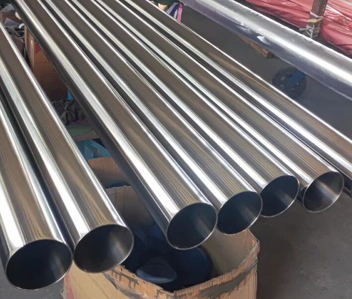
tablo 8: Maksimum Çalışma Basıncı Sınırları (çubuk) için 1.4301 Kaynaklı Konfigürasyonlar
| DN Boyutlandırma Kodu | 10 | 15 | 20 | 25 | 32 | 40 | 50 | 65 | 80 | 100 | 125 | 150 | 200 |
|---|---|---|---|---|---|---|---|---|---|---|---|---|---|
| Sınır: $20^\circ\text{C}$ (çubuk) | 355 | 242 | 200 | 159 | 131 | 112 | 87 | 87 | 72 | 59 | 47 | 39 | 30 |
| Sınır: $150^\circ\text{C}$ (çubuk) | 219 | 150 | 124 | 98 | 81 | 69 | 53 | 54 | 44 | 36 | 29 | 24 | 18 |
9. İç Yüzey Kaplama Topografyası & Mikro Pürüzlülük Sabitleri
İç yüzey topografyası üzerinde sıkı kontrolün sürdürülmesi, mikrobiyal büyümenin veya biyofilm yapışmasının önlenmesi için esastır.. Her iki standart da izin verilen maksimum dahili Pürüzlülük Ortalaması üzerinde katı sınırlamalar uygulamaktadır ($R_a$).
Yerinde Temizleme sırasında tekrarlanabilir temizlenebilirliği sağlamak için (CIP) süreçler, iç yüzey bir koruma sağlamalıdır $R_a \le 0.8\ \mu\text{m}$. Yüksek saflıkta ilaç sektörleri için, bitirme gereksinimleri ayrıca aşağıdakilerle sınırlıdır: $R_a \le 0.4\ \mu\text{m}$ veya daha iyisi, tipik olarak özel mekanik aşındırma ve ardından elektro-parlatma işlemi katmanı yoluyla elde edilir.
tablo 9: Yüzey Pürüzlülüğü Tanımları, Tedavi Protokolleri & Hedef Sınırları
| TR Kodu | Eski Kod | Süreç Durumu & Termal Tedavi | İç Gövde ($R_a\ \mu\text{m}$) | kaynaklı dikiş ($R_a\ \mu\text{m}$) | Dış Yüzey ($R_a\ \mu\text{m}$) |
|---|---|---|---|---|---|
| CL1 BC | M.Ö. | Parlak Tavlı, Mekanik olarak cilalanmış | ≤ 0.80 | ≤ 1.60 | salamura (≤ 1.60) |
| CL1 BD | BD | Parlak Tavlı, Dış Zemin | ≤ 0.80 | ≤ 1.60 | ≤ 1.00 |
| CL1 CC | CC | Tavlanmamış, Turşu Temiz | ≤ 0.80 | ≤ 1.60 | salamura (≤ 1.60) |
| CL1 CD'si | CD | Tavlanmamış, Harici Topraklama | ≤ 0.80 | ≤ 1.60 | ≤ 1.00 |
| Üç Yonca | 3Bir Özellik | Yüksek Saflıkta Elektro Cilalı Varyant | ≤ 0.38 | ≤ 0.38 | ≤ 0.80 |
10. Alternatif Yüzey Topografyası & Kum Parlatma Dönüşümü
Uluslararası malzemeleri değerlendiren satın alma bölümlerine yardımcı olmak, mekanik tanecik tanımlarının hassas metroloji değerlerine dönüştürülmesi esastır. Tane boyutu aşındırıcı ortamın parçacık yoğunluğunu ifade ederken, resmi sertifikasyon kriterleri gerçek pürüzlülük ölçümlerine dayanır ($R_a$) sıhhi uygunluğu doğrulamak için.
tablo 10: Mikron Pürüzlülüğüne Kadar Kum Aşındırıcı İşleme / Mikro-inç Dönüşüm
| Aşındırıcı Bitirme Formatı | Pürüzlülük ($R_a$, mikro inç) | Pürüzlülük ($R_a$, mikron) | ISO 4287 Tanım | Elektro-parlatma Cilası Son Kat Katmanı |
|---|---|---|---|---|
| 150 Kum Kaplama | 30 – 35 | 0.75 – 0.875 | N6 | Uygulanamaz |
| 150 kum + Elektropolisaj | 12 – 20 | 0.30 – 0.50 | N5 | Tamamen Uygulandı |
| 180 Kum Kaplama | 20 – 25 | 0.50 – 0.625 | N5 | Uygulanamaz |
| 180 kum + Elektropolisaj | 10 – 16 | 0.25 – 0.40 | N4 | Tamamen Uygulandı |
| 240 Kum Kaplama | 15 – 20 | 0.375 – 0.50 | N5 | Uygulanamaz |
| 240 kum + Elektropolisaj | 8 – 12 | 0.20 – 0.30 | N4 | Tamamen Uygulandı |
| 320 Kum Kaplama | 8 – 12 | 0.20 – 0.30 | N4 | Uygulanamaz |
| 320 kum + Elektropolisaj | 6 – 12 | 0.15 – 0.30 | Ultra Temiz | Tamamen Uygulandı |
11. Kalite Kontrol Protokolleri, Test Metodolojileri & Metroloji Standartları
EN ile uyumluluğun doğrulanması 10357 ve 11850 sıkı tahribatsız ve tahribatlı testler gerektirir. Mekanik Özellikler, kimyasal matrisler, ve yüzey parametrelerinin doğrulanması gerekir. TR 10217-7 Test Kategorisi 1 (TC1) tüzük, veya Test Kategorisi 2 (TC2) AD-2000-Merkblatt W2 koşulları altındaki protokoller.
Pürüzlülük testleri aşağıdaki şekilde gerçekleştirilir: EN ISO'NUZ 4287 ve EN ISO'NUZ 4288 protokoller. Denetçiler tüpün ucundaki yüzey parametrelerini ölçüyor, Kesinlikle $5\text{ mm}$ kenardan, minimum değerlendirme 1 içinde 20 her üretim ısısından gelen tüpler. Dışarıdan taşlanmış profiller için (CD ve BD türleri), oran ölçümleri en azından yapılır $100\text{ mm}$ Kenar parlatma distorsiyonunu ortadan kaldırmak için tüpün ucundan.
tablo 11: Zorunlu KG Denetim Testi Eşik Matrisi
| Hedef Test Ediliyor | Referans Normu | Usul Yöntemi / Kriterler | Minimum Frekans |
|---|---|---|---|
| Kaynak Dikiş Bütünlüğü | TR 10217-7 / ISO'DA 10893-1 | Sürekli tahribatsız Girdap Akımı testi veya Hidrostatik doğrulama döngüleri. | 100% Toplu |
| yüzey pürüzlülüğü ($R_a$) | EN ISO'NUZ 4287 / 4288 | Stylus profilometre ölçümü alındı $5\text{ mm}$ boru ucundan hem kaynak bölgesi hem de iç ana metal boyunca. | 5% Uzunluklar (1:20) |
| Boyutsal Uyumluluk | TR 10357 / DİN 11850 | Mikrometre dış çap onayı ve lazer duvar kalınlığı duvar taramaları. | 100% Toplu |
| Kaynak Deforme Edilebilirliği | ISO'DA 8492 / 8493 | Soğuk şekillendirme esnekliğini doğrulamak için yıkıcı halka düzleştirme ve sürüklenme genişletme testi. | Isı paketi başına bir kez |
12. Sistem İzlenebilirliği, Markalama Standartları & Değirmen Sertifikaları
Eksiksiz malzeme izlenebilirliği modern sıhhi mühendisliğin temelidir kalite güvence. Yüksek saflıkta işleme sektörlerinde, tam varlık takibi, herhangi bir hammadde kusurunun hızlı bir şekilde izole edilebilmesini sağlar, Üretim zinciri genelinde riski azaltmak.
Dokümantasyon bütünlüğünü korumak için, tüm borular üreticinin işaretiyle açıkça damgalanmalıdır, standart kodlar, Boyutlar, yüzey özellikleri, ve spesifik malzeme ısı numarası. Üstelik, teslimatlar sertifikalı bir ürün içermelidir TR 10204 3.1 Malzeme Test Raporu (MTR), Tam kimyasal bileşimin ve mekanik özelliklerin doğrulanması.
tablo 12: Zorunlu Damgalama ve Dokümantasyon Doğrulaması
| Gerekli İşaretleme Parametresi | Damgalama Sözdizimi Örneği | Doğrulama Gereksinimi |
|---|---|---|
| Menşe Takibi | DEĞİRMEN ADI ALMANYA | Üretim yerini ve yerini tanımlar. |
| Standart uyumluluk | EN 10357-A / DİN 11850 | Boyutsal alt sınıf çerçevesini doğrular. |
| Boyutsal Profil | DN50 $53.0 \times 1.5\text{ mm}$ | Dış çapı ve duvar kalınlığını doğrular. |
| Yüzey Yürütme Kodu | CL1 BD | Pürüzlülük sınıfı kriterlerini doğrular. |
| İzlenebilirlik Kimliği | ISI YOK. H2026X57 | Çelikhane parti profiline geri bağlantılar. |
13. Elastomerik Sızdırmazlık Uyumluluğu & Kimyasal Dayanım Profilleri
Güvenilir bir hijyenik proses sistemi oluşturmak, bağlantı bağlantılarını sızdırmaz hale getirmek için uyumlu elastomerik contaların seçilmesini gerektirir, sendika fındık, ve Tri-Clamp halkaları. Uygun olmayan elastomerik bileşikler agresif ürün kimyasına veya sert Yerinde Temizlemeye maruz kaldığında hızla bozunabilir (CIP) çözümler.
örneğin, standart Nitril Kauçuk (NBR) yüksek konsantrasyonlu sıcak kül suyu çevrimlerine veya aktif buhar hatlarına maruz kaldığında sınırlı direnç gösterir. Tersine, Etilen Propilen Dien Monomer gibi birinci sınıf polimerler (EPDM) veya Politetrafloroetilen (PTFE) Yoğun sterilizasyon ortamlarında malzeme bütünlüğünü koruyun, Contanın bozulmasını ve proses sıvısının kirlenmesini önleme.
tablo 13: Elastomerik Bileşikler için Kapsamlı Ürün ve Kimyasal Direnç Derecelendirmeleri
| Medya Türü veya İşlem Akışı | NBR | HNBR | EPDM | Silikon (Q) | FPM (Viton) | PTFE (Teflon) |
|---|---|---|---|---|---|---|
| Standart Süt Ürünleri (Süt, Krem) | 3 | 3-4 | 3-4 | 3-4 | - | 4 (yüksek) |
| Kültürlü Ekşi Süt Çeşitleri | 3 | 3-4 | 3-4 | 3-4 | - | 4 (yüksek) |
| Bira Fabrikası Akışları (Bira, Şerbetçiotu) | 3 | 3-4 | 3-4 | 1-2 | 2-3 | 4 (yüksek) |
| Şarap İşleme ve Mayalar | 3 | 3-4 | 4 | 4 | 2-3 | 4 (yüksek) |
| Hayvan & Bitkisel Yağlar (Hedef $100^\circ\text{C}$) | 3 | 4 | 1-2 | 3 | 4 | 4 (yüksek) |
| Sıcak Proses Suyu / buhar (Hedef $130^\circ\text{C}$) | 1 (Hata) | 4 | 4 | 2 | - | 4 (yüksek) |
| Oksitleyici Olmayan Asitler (Hedef $80^\circ\text{C}$) | 1-2 | 2 | 3 | 1-2 | 2 | 3-4 |
| Zayıf Alkali Kostik Karışımları (Hedef $100^\circ\text{C}$) | 2 | 3-4 | 4 | 2 | 2 | 4 (yüksek) |
| Konsantre CIP Kostik Temizleyiciler | 1 (Hata) | 2-3 | 3 | 1 | 1 | 4 (yüksek) |
* Not: Performans indeksleme değerleri global ISO R'ye uygun olarak derlenir 1629 kauçuk sınıflandırma kuralları. (Anahtar: 4 = Yüksek Uygunluk; 3 = Normal Uygunluk; 2 = Sınırlı Uygunluk; 1 = Uygun değil).
14. İç Geometrik Alan & Hacimsel Yer Değiştirme Matrisleri
Kesin sıvı deplasmanını hesaplamak için iç çapın tam olarak analiz edilmesi gerekir ($d_i$) boru hattının. Çünkü duvar kalınlığı parametreleri farklı yapısal serilere göre değişiklik göstermektedir., A Grubu ve C Grubu sınıfları arasında iç kesit alanı önemli ölçüde değişmektedir..
Hijyenik proses tasarımı, akış direncinin en aza indirilmesini ve optimum basınç koşullarının korunmasını gerektirir. Aşağıdaki tablo, temel standart nominal çap segmentlerindeki gerçek iç kesit alanlarını ve bağıl sıvı kapasitelerini özetlemektedir..
tablo 14: Gerçek İç Kesit Alanı ve Kapasite Endeksi Matrisi
| Boyutlandırma İndeksi (DN) | Standart Dış Çap (mm) | Duvar Sınıfı (mm) | Gerçek Kimlik ($d_i$, mm) | İç Alan ($\text{cm}^2$) | Birim Sıvı Hacmi. (L/dak) |
|---|---|---|---|---|---|
| DN 25 | 29.0 | 1.5 | 26.0 | 5.31 | 0.531 |
| 2.0 | 25.0 | 4.91 | 0.491 | ||
| DN 50 | 53.0 | 1.5 | 50.0 | 19.63 | 1.963 |
| 2.0 | 49.0 | 18.86 | 1.886 | ||
| DN 100 | 104.0 | 2.0 | 100.0 | 78.54 | 7.854 |
| 2.5 | 99.0 | 76.97 | 7.697 |
15. Kaynak Özellikleri & ısıdan etkilenen bölge (HAZ) Emniyet
Akış yolunu pürüzsüz ve kesintisiz tutarken hijyenik hatları bağlamak için, otomatik yörüngesel TIG kaynağı yaygın olarak kullanılmaktadır. Yüksek bir seviyeye ulaşmak-kalite eklem, tanecik sınırları boyunca krom karbür çökelmesini önlemek için ısı girişinin yönetilmesini gerektirir.
Kaynak sırasında borunun içindeki uygun oksijen yönetimi kritik öneme sahiptir. Yüksek saflıkta argon destek gazı kullanma ($>99.995\%$) boşaltma odasında düşük oksijen seviyelerini korur, Pasif yüzey katmanını tehlikeye atabilecek ve korozyona yol açabilecek oksit renk bozulmasını ortadan kaldırır.
tablo 15: Orbital TIG Kaynak Parametreleri & Koruma Protokollerini Temizleme
| Kaynak Parametresi | Operasyonel Hedef & Kontrollü Ayarlar | Hedef Değer Metriği |
|---|---|---|
| Oksijen Sınırını Temizleme | Ark dizisini başlatmadan önce dahili temizleme yolu içinde izin verilen maksimum oksijen konsantrasyonu. Kaynak kökü oksidasyonunu önler. | ≤ 25 ppm |
| Koruyucu Gaz Saflığı | Torç ve destek gazı bileşimi. Kaynak gözenekliliğini önlemek için tamamen hidrokarbonlardan ve nemden arınmış olmalıdır. | 99.995% Argon dk.. |
| Doğrusal Isı Girişi | Kaynak sırasında birim uzunluk başına verilen enerji. Mikroyapısal dengeyi korumak ve tane büyümesini önlemek için kontrol edilir. | 0.5 – 1.2 KJ/mm |
| Yanlış Hizalama Limiti | Bağlantı yerinde eşleşen boru duvarları arasında izin verilen maksimum adım yüksekliği. Proses sıvısını tutabilecek dahili çatlakları önler. | ≤ 10% duvar kalınlığı |
16. Yerinde Lojistik, Depolama Protokolleri & Kurulum Hizalama Kriterleri
Hijyenik boruların hassas toleranslarının ve yüzey kalitesinin korunması, nakliye ve yerinde depolama sırasında malzemenin dikkatli bir şekilde taşınmasını gerektirir.. Galvanik kirlenmeyi önlemek için, paslanmaz çelik profiller karbon çeliği bileşenlerden ayrı olarak depolanmalıdır.
Noktasal yük deformasyonunu önlemek için borular ahşap destek şeritleri veya yastıklı raflarla desteklenmelidir.. Ayrıca, Tam kendi kendine drenaj performansını garanti etmek için yüksek saflıkta hatlar tutarlı bir eğim eğimiyle kurulmalıdır, sistem hijyenini tehlikeye atabilecek sıvı sıkışma bölgelerinin ortadan kaldırılması.
tablo 16: Depolama ve Sahada Taşıma Gereksinimleri
| Taşıma Aşaması | Zorunlu Prosedür & Koruma Kriterleri | Hedef Limit Metriği |
|---|---|---|
| Depo Depolama | İç mekanda yastıklı raflarda saklayın, karbon çeliğinden izole edilmiştir. Havadaki tozu engellemek için koruyucu plastik uç kapaklarını sıkıca yerinde tutun. | 100% kuru ortam |
| Kaldırma Lojistiği | Taşıma sırasında temiz naylon askılar veya polimer kaplı kancalar kullanın. Paslanmaz boru demetleri üzerinde asla çıplak çelik zincirleri veya forkliftleri doğrudan kullanmayın.. | Sıfır yüzey puanlaması |
| Drenaj Hizalaması | Temizleme döngüleri sırasında sistemin tamamen boşaltılmasını sağlamak için yatay yollar drenaj vanalarına doğru aşağıya doğru eğimli olmalıdır.. | min. eğim 1:100 (1%) |
17. Tahribatsız test (NDT) & Metalurjik Bütünlük Doğrulaması
Avrupa gıdasını düzenleyen katı standartlara uyumu sağlamak, Günlük, ve farmasötik üretim matrisi, EN'nin her üretim çalışması 10357 / DİN 11850 tüpler sıkı bir dahili tahribatsız test matrisinden geçmelidir. Bu prosedürler döngüsel termal gerilim altında yapısal dayanıklılığı garanti eder ve yüksek proses basınçlarında iğne deliği sızıntısı riskini ortadan kaldırır.
Çevrimiçi olarak dağıtılan birincil metodoloji: 100% EN ISO ile tam uyumlu otomatik girdap akımı testi 10893-1 veya EN ISO 10893-2. Bu elektromanyetik test sistemi, hem ana metal matrisin hem de otojen ergitme kaynak hattının sürekliliğini hızlı bir şekilde değerlendirir., mikroskobik uzunlamasına duvar çatlaklarının izole edilmesi, cüruf kalıntıları, veya çıplak gözle görülemeyen iç gaz cepleri.
tablo 17: Zorunlu Kalite Kontrol Matrisi ve Kabul Kriterleri
| Test Kategorisi | Test Metodolojisi & Referans Yönetmeliği | Zorunlu Kabul Standardı |
|---|---|---|
| Girdap Akımı Kusur Tespiti | EN ISO'ya uygun olarak ana şerit ve dikiş kaynak bölgesi bütünlüğünü hedefleyen sürekli hat içi elektromanyetik değerlendirme 10893-2. | Sıfır sinyal sapması (Çatlak yok) |
| Mekanik Kaynak Düzleştirme | EN ISO'ya göre kaynak düzlemine göre 90° yönelimde numune kuponlarının ciddi basınç deformasyonu yoluyla yıkıcı değerlendirme 8492. | Mikro çatlak veya kaynak çatlağı yok |
| Boyutsal Lazer Denetimi | Nominal dış çap tekdüzeliğini ve kesit yuvarlaklığını doğrulamak için sürekli yüksek hızlı 360 derece temassız lazer telemetri. | Kesinlikle EN içinde 10357 Mektup |
18. Üretim Sonrası Kimyasal Pasivasyon & Yüzey Kimyası Optimizasyonu
Maksimum lokalize çukurlaşma direnci eşdeğerine ulaşmak için (ODUN) süreç ağlarındaki metrikler, bitmiş östenitik ve dubleks hijyenik çelik borular hassas kimyasal daldırma pasivasyonuna tabi tutulur. Bu metalurjik işlem, borunun iç duvarına gömülü eser element içermeyen demiri ham mekanik çekme ve cilalama ortamından uzaklaştırır..
Ultra pürüzsüz yüzeylerin hedeflenen nitrik asit formülasyonlarıyla temas ettirilmesiyle ($HNO_3$) veya organik sitrik asit, yüzey krom konsantrasyonu demire göre yapay olarak artar. Bu süreç sürekli bir oluşumu hızlandırır., yapışkan krom oksit ($Cr_2O_3$) pasif bariyer katmanı. Bu moleküler bariyer, sıcak kostik soda veya asit dezenfektanları içeren agresif CIP temizleme ortamından gelen iyonik nüfuzu etkili bir şekilde engeller.
tablo 18: Standart Endüstriyel Kimyasal Pasivasyon Parametreleri
| Kimyasal Formülasyon | Hacimsel Çözüm Sıcaklığı. | Daldırma Süresi | Hedef Geçiş Pasif Oranı |
|---|---|---|---|
| Nitrik asit (20% – 25% $HNO_3$) | 45° C – 55° C | 20 – 30 dakika | CR:Fe Oranı ≥ 1.5 XPS aracılığıyla |
| Sitrik asit (4% – 10% Şelasyon) | 50° C – 65° C | 30 – 45 dakika | CR:Fe Oranı ≥ 1.2 XPS aracılığıyla |
19. Düzenleyici İzlenebilirlik & Malzeme Sertifikasyon Standartları
Steril işleme ortamlarında, Maddi köken ve yapısal şeffaflık tartışılamaz yasal zorunluluklardır. EN'ye göre üretilmiş tüm boru malzemeleri 10357 Birincil eritme aşamasından son bitirme işlemlerine kadar kesintisiz yapısal izleme sürdürülmelidir. Her parti, boru profilinin dış uzunluğu boyunca silinmez lazer işaretleme yoluyla belirli hadde ısı numaralarına çapraz referanslıdır..
Sistem denetçilerinin yapısal onayını güvence altına almak için, Teslimat evraklarında resmi bir EN yer almalıdır 10204 Türü 3.1 muayene sertifikası. Bu belge, pota numunesi kimyasal konfigürasyonlarını izler, doğru mekanik arıza ölçümleri (akma güçleri dahil $R_{p0.2}$, nihai çekme limitleri $R_m$, ve yüzde uzama $A$), ve belgelenmiş iç duvar mikrometre pürüzlülüğü ($R_a$) Parametreler.
tablo 19: Düzenleyici İzlenebilirlik Çerçeve Standartları
| Düzenleyici Mekanizma | Doğrulama Kapsamı & İzleme Özellikleri | Uyumluluk Düzeyi |
|---|---|---|
| TR 10204 Türü 3.1 sertifika | Bağımsız test denetçilerinden gerçek fiziksel değirmen mekanik sonuçlarını ve kimyasal değerleri listeleyen zorunlu doğrulama. | Tamamen İzlenebilir Isı Takipli |
| EC No 1935/2004 Hizalama | Alaşım formülasyonunun, operasyonel temas sırasında tehlikeli ağır elementleri sıvı gıda akış akışlarına sızdırmayacağını doğrular. | Gıdayla Temas Onaylı |
| Sürekli Lazer Kalıplama | Standart referans kodlarını belirten kalıcı yapısal yüzey işaretlemesi, doğru boyutlar, çelik sınıfı adı, ve birincil ısı kodu. | 100% Sahada Tanımlama |
20. CIP/SIP Protokolü Uyumluluğu & Önleyici Bakım Kimyaları
Ultra düşük iç yüzey pürüzlülüğünün korunması ($R_a \le 0.40\,\mu\text{m} – 0.80\,\mu\text{m}$) EN'nin 10357 Çok yıllık üretim kampanyaları boyunca hijyenik boru hatları, standartlaştırılmış Yerinde Temizleme kurallarına sıkı sıkıya bağlı kalmayı gerektirir (CIP) ve Yerinde Buhar (YUDUM) termal rejimler. Uygun olmayan kimyasal maruz kalma veya yetersiz sıvı hızları lokalize yaralanmalara neden olabilir. “aldanma”—pasif krom oksit katmanını bozan mikro ölçekli demir oksit veya hidroksit filmlerinin oluşumu.
Organik kalıntıları iyice temizlemek ve çukurlaşma korozyonuna neden olmadan biyolojik matrisleri nötralize etmek için, işleme hatları, formüle edilmiş alkalin deterjanlar ve asidik nötrleştirici durulamalardan oluşan alternatif bir döngüyle karşılaşmalıdır. Üstelik, 134°C'ye kadar doymuş buhar kullanan SIP operasyonları, termal genleşme değişkenlerinin dikkatli bir şekilde izlenmesini gerektirir ($16.5 \times 10^{-6}/\text{K}$ için 1.4404 Çelik) iç yörüngesel kaynak dikişleri boyunca mekanik gerilimi ortadan kaldırmak için.
tablo 20: Standart CIP/SIP Operasyonel Döngü Eşikleri
| İşletme Aşaması | Kimyasal bileşimi / Orta | Termal Aralık | Hedef Kinetik Eşiği |
|---|---|---|---|
| Alkali CIP Yıkama | Sodyum Hidroksit ($NaOH$) 1.0% – 2.0% WT. | 75° C – 85° C | min. hız: 1.5 m/sn |
| Asit CIP Durulama | Nitrik asit ($HNO_3$) 0.5% – 1.0% WT. | 50° C – 60° C | Pasivasyon Bakımı |
| SIP Termal Döngüsü | Doymuş Temiz Buhar (Kuruluk > 95%) | 121° C – 134° C | Maruziyet: 20 – 30 dakika |
21. Akışkan dinamiği & Sınır Katmanı Mekanik Hususlar
Mühendislik perspektifinden, EN tarafından tanımlanan iç boyut matrisleri 10357 (A'dan D'ye kadar seriler) türbülanslı akış profillerini ve sınır tabakası kayma gerilimini kontrol etmek için matematiksel olarak optimize edilmiştir. Yüksek viskoziteli gıda karışımları veya kesilmeye duyarlı biyolojik materyaller hijyenik bir ağdan geçtiğinde, pürüzsüz duvar tasarımı basınç düşüşlerini en aza indirir ve dahili cep ayrılmasını önler.
Tam gelişmiş bir türbülanslı akış rejiminin sürdürülmesi (Reynolds numarası $Re > 4000$) CIP uygulaması sırasında biyofilmi mekanik olarak yerinden çıkarmak için gerekli duvar kesme gerilimini oluşturmak esastır.. Çünkü A Serisinin kesit geometrisi metrik pompalar ve bağlantı parçalarıyla tam olarak eşleşir, proses tesisleri eşmerkezli redüktörlerin kullanımını en aza indirebilir, alttaki pasif krom yüzeylerini aşındıran türbülansın neden olduğu kavitasyon noktalarının azaltılması.
tablo 21: Nominal Boyutlara Göre Hidrolik Değerlendirme Parametreleri (SERİSİ A)
| Nominal boyut | İç Çap ($D_i$) | Akış Alanı Kesiti | Hedef Hacim Oranı (de 1.5 m/sn) |
|---|---|---|---|
| DN25 | 26.0 mm | 530.9 $\text{mm}^2$ | ~ 2.87 $\text{m}^3/\text{h}$ |
| DN40 | 38.0 mm | 1134.1 $\text{mm}^2$ | ~ 6.12 $\text{m}^3/\text{h}$ |
| DN50 | 50.0 mm | 1963.5 $\text{mm}^2$ | ~ 10.60 $\text{m}^3/\text{h}$ |
| DN100 | 100.0 mm | 7854.0 $\text{mm}^2$ | ~ 42.41 $\text{m}^3/\text{h}$ |
Kimyasal bileşimler, yapısal parametreler, Bu dizindeki boyutsal konfigürasyonlar resmi Avrupa standartlarına uygundur. Proses yerleşimlerini veya boru sistemi mühendislik hesaplamalarını tamamlamadan önce, İşletme tarafından verilen EN'ye göre bireysel gereklilikleri doğrulayın 10204 3.1 muayene sertifikası.
Olmalısın giriş Yorum yazmak için.