
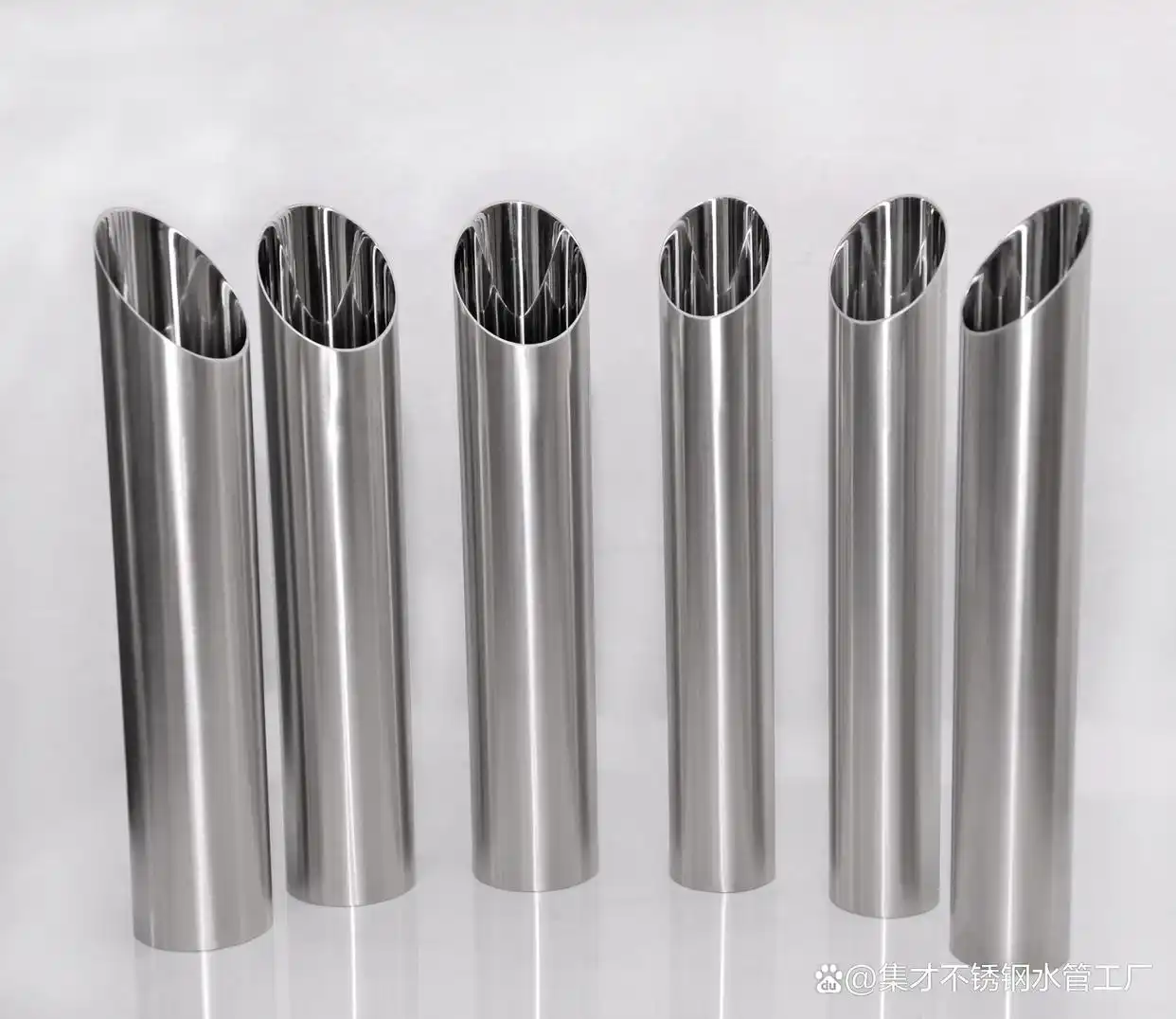
1. à partir de DIN 11850 deux UN 10357
Dans l'exécution de systèmes de processus industriels de haute pureté, l'intégration de composants structurels qui éliminent les voies d'accumulation microbactériennes est obligatoire. Depuis des décennies, la norme industrielle allemande DIN 11850 a servi de cadre d'ingénierie dominant dans toute l'Europe continentale, définir les conditions techniques de livraison, tolérances spatiales, et dimensions géométriques pour les tubes en acier inoxydable sans soudure et soudés utilisés dans l'industrie alimentaire, Laitier, Chimique, et installations de traitement pharmaceutique.
Éliminer les barrières commerciales régionales et unifier les normes de fabrication sanitaires dispersées et spécifiques à chaque pays dans un cadre réglementaire européen commun., le Comité européen de normalisation a officiellement promulgué FR 10357 au début de 2014. Cette norme européenne a harmonisé avec succès les conditions techniques préalables aux canalisations hygiéniques dans tous les États membres de l'Union européenne., établir une base de référence standardisée pour l'architecture de gestion des fluides.
Note d'ingénierie stratégique: Bien que FR 10357 sert de successeur légal formel du DIN 11850, les systèmes structurels existants et les spécifications d'approvisionnement actuelles font fréquemment référence aux dimensions DIN. Par conséquent, les lignes de fabrication modernes doivent fonctionner en parfaite conformité avec les deux normes, maintenir des sous-classes dimensionnelles pour s'adapter aux protocoles d'ingénierie régionaux.
Dans le cadre de l'ingénierie d'aménagement hygiénique, une distinction nette doit être faite entre les tuyaux destinés aux processus sanitaires généraux (nourriture et boisson) et ceux conçus pour une aseptie stricte, applications stériles (biotechnologie et pharmaceutique). Pendant le din 11850 et FR 10357 se concentrer principalement sur les paramètres des tubes sanitaires, les raccords correspondants, les syndicats, et les matrices de composants sont régies par des couches standard distinctes.
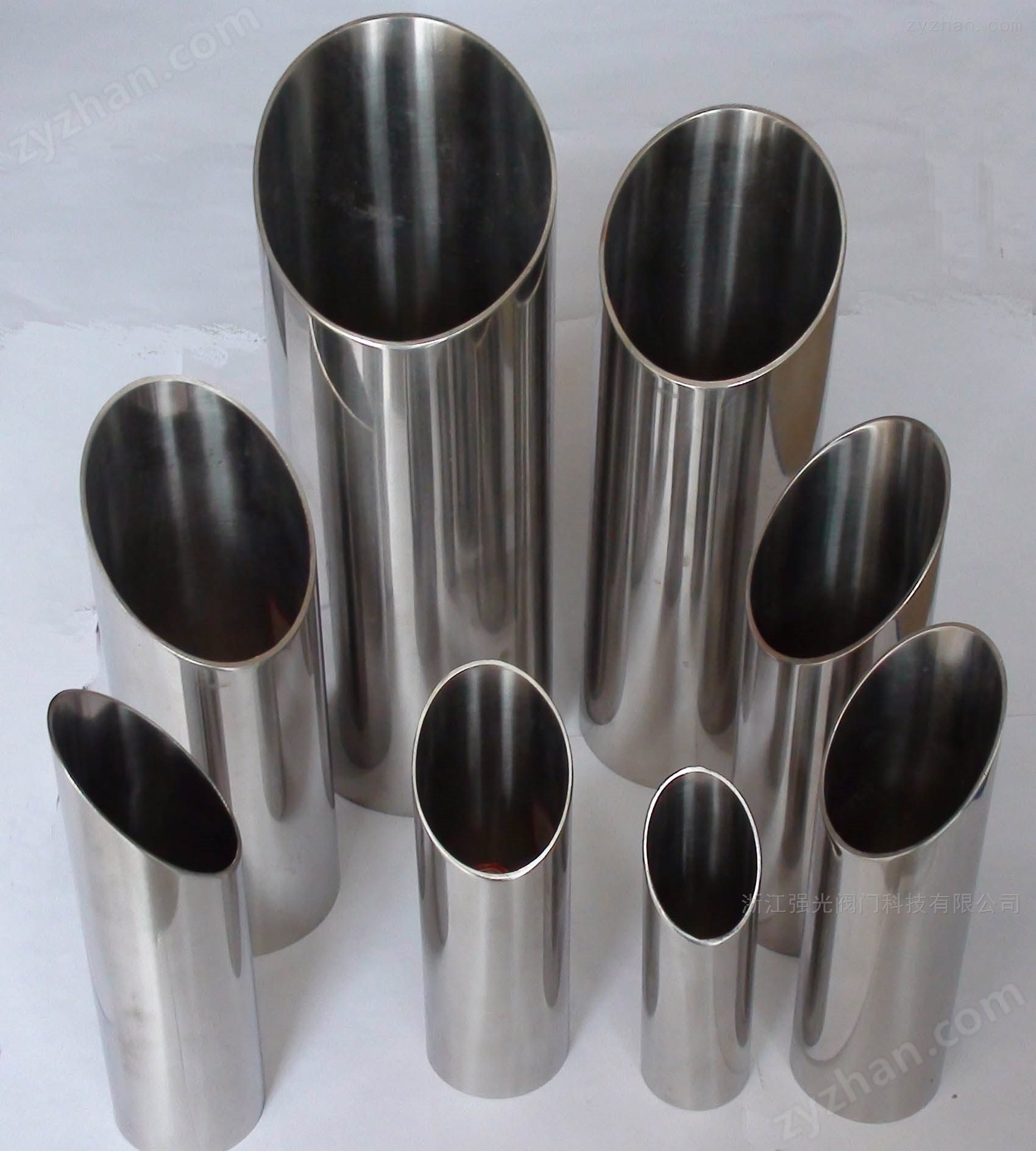
Table 1: Matrice de références croisées européenne pour les tubes, ACCESSOIRES, et classifications aseptiques
| Catégorie d'application | Dimensions des tubes & spécifications | ACCESSOIRES & Connexions | Segments industriels cibles |
|---|---|---|---|
| Sanitaires standards / Hygiénique | DIN 11850 (Héritage) | DIN 11851 (vissé) DIN 11852 (Soudage) DIN 11853 (Syndicats hygiéniques) |
Transformation des produits laitiers, Brasseries, Boisson, Transport alimentaire fluide, Produits de beauté |
| FR 10357 (Norme actuelle) | |||
| Aseptique de haute pureté & Stérile | DIN 11866 | DIN 11864 (Unions aseptiques) DIN 11865 (Raccords aseptiques) |
Biotechnologie, Ingrédients pharmaceutiques actifs (API), Génétique, Fabrication de semi-conducteurs |
2. Géométrie métrique, Sous-classes structurelles, et harmonisation multinormes
Gérer les différentes dimensions physiques utilisées dans des écosystèmes industriels mondiaux distincts, FR 10357 structure sa portée en sous-classes dimensionnelles très distinctes. Ces désignations permettent aux équipes d'ingénierie de vérifier rapidement si un lot de production respecte les normes métriques européennes traditionnelles., Conventions américaines sur les bioprocédés de haute pureté, ou index de tailles internationaux.
- EN 10357-A (SÉRIE A): Suit les dimensions héritées initialement dictées par DIN 11850. Il s'agit du principal cadre métrique utilisé pour les usines laitières et brassicoles automatisées européennes..
- EN 10357-C (Série C): Calibré pour s'adapter aux diamètres extérieurs et aux épaisseurs de paroi dictés par la norme américaine ASME BPE (Équipement de bioprocédés) mesures de dimensionnement, optimisation des lignes pour l'assemblage de skids modulaires transcontinentaux.
- EN 10357-D (Série D): Formulé en alignement direct avec l'ISO internationale 2037 Dimensions, servir de norme de base pour les systèmes utilisant des chaînes d'approvisionnement mondiales alternatives en composants.
Un écart structurel mineur entre l'ancien DIN 11850 spécifications et la norme EN unifiée 10357 réside dans la documentation formelle des limites dimensionnelles pour des tronçons de tuyauterie exceptionnellement grands. Spécifiquement, FR 10357 introduit des limites de tolérance de fabrication précises pour $254\text{ mm}$ tubes de diamètre extérieur (DN 250), une enveloppe de dimension extérieure qui manquait d'un, spécification structurelle explicite dans le texte standard allemand historique.
Table 2: Comparaison dimensionnelle & Déviations structurelles
| Paramètre d'évaluation | DIN 11850 Spécification du | FR 10357 Spécification du |
|---|---|---|
| Base de référence de dimensionnement | Diamètre nominal exclusivement métrique (DN) directement lié à des tailles fixes en millimètres. | Framework tri-split englobant Metric (SÉRIE A), ASME-BPE (Série C), et ISO 2037 (Série D). |
| De Grand Diamètre enveloppe ($254\text{ mm}$) | Non explicitement spécifié / laissé à l'accord de chaque usine. | Formellement standardisé avec des limites de tolérance structurelle définies à $\pm 0.4\text{ mm}$. |
| Nomenclature de finition de surface | Utilise des codes d’exécution directe: CC, CD, Colombie-Britannique, BD. | Combine la classe structurelle et les codes d'exécution: Classe 1 (CL1) ou Classe 2 (NC2) + CC/CD/BC/BD. |
| Critères de pression interne | Calcule officiellement les allocations maximales de barre à $20^\circ\text{C}$ et $150^\circ\text{C}$. | Omis du texte standard officiel (se conforme aux normes externes relatives aux récipients sous pression comme EN 13480). |
| Limite de contrainte de rectitude | Identique dans les deux codes: $0.0015 \times \text{Length}$, avec un plafond de déflexion maximum de $2\text{ mm}$ par mètre linéaire simple. |
3. Caractérisation métallurgique & Seuils de composition chimique
Les performances mécaniques et la résistance à la corrosion des systèmes sanitaires dépendent fortement de configurations précises d'alliage d'acier.. Matériaux sous DIN 11850 et FR 10357 doit provenir de variantes d'acier inoxydable austénitique de première qualité synthétisées selon la norme EN 10088-2 Critères. Les principaux alliages utilisés sont 1.4301 (AISI 304), 1.4307 (AISI 304L), et 1.4404 (AISI 316L).
Pour atténuer les risques de corrosion intergranulaire dans les zones de fluide chauffé ou à proximité des points de soudure orbitaux à haute température, variantes à faible émission de carbone ($C \le 0.035\%$) sont explicitement spécifiés pour 1.4307 et 1.4404 tableaux. en outre, l'inclusion de molybdène ($2.0\% – 3.0\%$) au sein de 1.4404 la formulation garantit une résistance critique contre la corrosion localisée par piqûres et fissures lors de la manipulation de flux de processus acides, solutions de nettoyage, ou milieux à haute salinité.
Table 3: Limites de composition chimique très précises (ÉLÉMENT % par la messe)
| FR Code des alliages | Équivalent AISI. | CARBONE (C) | chrome (Cr) | nickel (Ni) | Molybdène (Mo) | manganèse (Mn) | Silicium (Si) | le phosphore (P) | soufre (S) |
|---|---|---|---|---|---|---|---|---|---|
| 1.4301 | 304 | ≤ 0.07 | 17.5 – 19.5 | 8.0 – 10.5 | - | ≤ 2.00 | ≤ 1.00 | ≤ 0.045 | ≤ 0.015 |
| 1.4307 | 304L | ≤ 0.030 | 17.5 – 19.5 | 8.0 – 10.5 | - | ≤ 2.00 | ≤ 1.00 | ≤ 0.045 | ≤ 0.015 |
| 1.4404 | 316L | ≤ 0.030 | 16.5 – 18.5 | 10.0 – 13.0 | 2.00 – 2.50 | ≤ 2.00 | ≤ 1.00 | ≤ 0.045 | ≤ 0.015 |
4. Propriétés de traction & Limites des performances mécaniques
Les tuyaux hygiéniques doivent posséder un équilibre robuste entre des limites de traction structurelle élevées et une ductilité matérielle exceptionnelle.. Ce profil permet aux lignes d'absorber en toute sécurité les chocs thermiques liés aux processus de nettoyage séquentiels sans se fissurer ni subir de défaillance structurelle..
Vérification mécanique, régi par les paramètres de test décrits dans ASME SA270 et EN 10217-7, exige que tous les composants structurels soient soumis à un protocole thermique de recuit en solution contrôlé. Chauffé entre $1040^\circ\text{C}$ et $1100^\circ\text{C}$ suivi d'une trempe rapide à l'eau ou à l'air, la microstructure se transforme en un continu, matrice austénitique non magnétique qui fournit des valeurs d'allongement prévisibles.
Table 4: Propriétés mécaniques certifiées & Conditions de recuit de solution
| Spécification matérielle | min. Limite d’élasticité ($R_{p0.2}$, MPa) |
Force De Traction ($R_m$, MPa) |
min. Élongation ($A_5$, %) |
température de recuit de solution ($^\circ\text{C}$) |
|---|---|---|---|---|
| FR 1.4301 / AISI 304 | 205 | 515 – 720 | 35% | 1040 – 1100 |
| FR 1.4307 / AISI 304L | 170 | 485 – 670 | 35% | 1040 – 1100 |
| FR 1.4401 / AISI 316 | 205 | 515 – 720 | 35% | 1040 – 1100 |
| FR 1.4404 / AISI 316L | 170 | 485 – 670 | 35% | 1040 – 1100 |
5. Groupe de matrice dimensionnelle A: Profils d’épaisseur de paroi légère ($1.0\text{ mm}$)
Les profils à paroi légère sont optimisés pour la distribution de fluides à basse pression ou les conduites d'alimentation par gravité à température ambiante où la réduction du poids du système est essentielle.. Ces configurations sont fréquemment intégrées dans des zones de stockage de produits à fort volume, réseaux de dérivation de distribution, et applications de ventilation secondaire dans les usines laitières automatisées.
Table 5: Groupe A (Mur de lumière) – Dimensionnement Nominal & Constantes de masse exactes
| Indice nominal (DN) | Tube OD ($d_e$, mm) | Depuis la tolérance (mm) | Épaisseur de paroi ($s$, mm) | Tolérance WT | Surépaisseur de coupe en bout | Masse théorique ($M$, kg/m) |
|---|---|---|---|---|---|---|
| DN 10 | 12.0 | ± 0.12 | 1.0 | ± 10% | +3.0 mm / -0.0 | 0.273 |
| DN 15 | 18.0 | ± 0.12 | 1.0 | ± 10% | +3.0 mm / -0.0 | 0.423 |
| DN 20 | 22.0 | ± 0.12 | 1.0 | ± 10% | +3.0 mm / -0.0 | 0.523 |
| DN 25 | 28.0 | ± 0.12 | 1.0 | ± 10% | +3.0 mm / -0.0 | 0.672 |
| DN 32 | 34.0 | ± 0.12 | 1.0 | ± 10% | +3.0 mm / -0.0 | 0.821 |
| DN 40 | 40.0 | ± 0.12 | 1.0 | ± 10% | +3.0 mm / -0.0 | 0.971 |
| DN 50 | 52.0 | ± 0.20 | 1.0 | ± 10% | +3.0 mm / -0.0 | 1.271 |
6. Groupe de matrice dimensionnelle B: Profils d'épaisseur de paroi standard ($1.5\text{ mm} – 2.0\text{ mm}$)
La configuration du profil intermédiaire du groupe B équilibre une résistance structurelle élevée avec une efficacité légère.. Cette section gère les normes municipales, Pharmaceutique, et pressions de fonctionnement des usines chimiques, ce qui en fait le format dimensionnel principal pour les systèmes de traitement de l'eau, lignes de transport de produits, et architecture générale de prise en charge des produits bruts.
Table 6: Groupe B (Mur standard) – Dimensionnement métrique complet et index de masse
| Indice nominal (DN) | Tube OD ($d_e$, mm) | Depuis la tolérance (mm) | Épaisseur de paroi ($s$, mm) | Tolérance WT | Portée de longueur linéaire (m) | Masse théorique ($M$, kg/m) |
|---|---|---|---|---|---|---|
| DN 10 | 13.0 | ± 0.30 | 1.5 | ± 10% | 6.00 | 0.431 |
| DN 15 | 19.0 | ± 0.30 | 1.5 | ± 10% | 6.00 | 0.655 |
| DN 20 | 23.0 | ± 0.30 | 1.5 | ± 10% | 6.00 | 0.805 |
| DN 25 | 29.0 | ± 0.30 | 1.5 | ± 10% | 6.00 | 1.030 |
| DN 32 | 35.0 | ± 0.30 | 1.5 | ± 10% | 6.00 | 1.255 |
| DN 40 | 41.0 | ± 0.30 | 1.5 | ± 10% | 6.00 | 1.480 |
| DN 50 | 53.0 | ± 0.30 | 1.5 | ± 10% | 6.00 | 1.931 |
| DN 65 | 70.0 | ± 0.30 | 2.0 | ± 10% | 6.00 | 3.400 |
| DN 80 | 85.0 | ± 0.30 | 2.0 | ± 10% | 6.00 | 4.150 |
| DN 100 | 104.0 | ± 0.30 | 2.0 | ± 10% | 6.00 | 5.101 |
| DN 125 | 129.0 | ± 0.40 | 2.0 | ± 10% | 6.00 | 6.350 |
| DN 150 | 154.0 | ± 0.40 | 2.0 | ± 10% | 6.00 | 7.601 |
| DN 200 | 204.0 | ± 0.40 | 2.0 | ± 10% | 6.00 | 10.100 |
| DN 250 | 254.0 | ± 0.40 | 2.0 | ± 10% | 6.00 | 12.601 |
7. Groupe de matrice dimensionnelle C: Profils à paroi épaisse ($2.0\text{ mm} – 2.5\text{ mm}$)
Pour les zones de traitement à haute température, boucles de vapeur stériles, ou conduites transportant des composés chimiques hautement corrosifs, s’appuyer sur des structures légères présente des risques opérationnels. Les configurations à paroi épaisse du groupe C offrent le facteur de sécurité en cas de pression d'éclatement nécessaire pour les réseaux de pasteurisation à plusieurs étages, lignes d'évaporation à grande vitesse, et des installations modernes de traitement chimique.
Table 7: Groupe C (Mur lourd) – paramètres géométriques & Valeurs de masse
| Indice nominal (DN) | Tube OD ($d_e$, mm) | Depuis la tolérance (mm) | Épaisseur de paroi ($s$, mm) | Tolérance WT | Fin de la contrainte d'équerrage | Masse théorique ($M$, kg/m) |
|---|---|---|---|---|---|---|
| DN 10 | 14.0 | ± 0.30 | 2.0 | ± 10% | ≤ 0.5% de la DO | 0.601 |
| DN 15 | 20.0 | ± 0.30 | 2.0 | ± 10% | ≤ 0.5% de la DO | 0.901 |
| DN 20 | 24.0 | ± 0.30 | 2.0 | ± 10% | ≤ 0.5% de la DO | 1.102 |
| DN 25 | 30.0 | ± 0.30 | 2.0 | ± 10% | ≤ 0.5% de la DO | 1.402 |
| DN 32 | 36.0 | ± 0.30 | 2.0 | ± 10% | ≤ 0.5% de la DO | 1.703 |
| DN 40 | 42.0 | ± 0.30 | 2.0 | ± 10% | ≤ 0.5% de la DO | 2.003 |
| DN 50 | 54.0 | ± 0.30 | 2.0 | ± 10% | ≤ 0.5% de la DO | 2.604 |
8. Seuils de pression interne hydrostatique & Calculs structurels
Contrairement aux anciennes règles allemandes, FR 10357 ne définit pas explicitement les limites de pression interne dans son texte principal, s'en remettre aux règles régionales de conception des appareils sous pression. cependant, pour garantir les facteurs de sécurité structurels, les équipes d'ingénierie s'appuient sur les formules de base enregistrées dans DIN 11850 et fiche d'information AD B1/B9.
Les calculs de capacité structurelle de base évaluent un segment de coque cylindrique sans découpes. ($P_{max}$), en supposant un 100% joint soudé longitudinal efficace. Parce que l'acier austénitique se ramollit à des températures plus élevées, les pressions nominales doivent être réduites jusqu'à 40% lors d'une utilisation sous stérilisation sur place (SIROTER) conditions à $150^\circ\text{C}$.
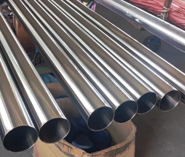
Table 8: Limites de pression de service maximale (bar) pour 1.4301 Configurations soudées
| Code de dimensionnement DN | 10 | 15 | 20 | 25 | 32 | 40 | 50 | 65 | 80 | 100 | 125 | 150 | 200 |
|---|---|---|---|---|---|---|---|---|---|---|---|---|---|
| Limite à $20^\circ\text{C}$ (bar) | 355 | 242 | 200 | 159 | 131 | 112 | 87 | 87 | 72 | 59 | 47 | 39 | 30 |
| Limite à $150^\circ\text{C}$ (bar) | 219 | 150 | 124 | 98 | 81 | 69 | 53 | 54 | 44 | 36 | 29 | 24 | 18 |
9. Topographie de finition de surface interne & Constantes de microrugosité
Maintenir un contrôle strict de la topographie des surfaces internes est essentiel pour prévenir la croissance microbienne ou la fixation de biofilms.. Les deux normes imposent des limitations strictes sur la moyenne de rugosité interne maximale autorisée. ($R_a$).
Pour garantir une nettoyabilité reproductible pendant le nettoyage en place (CIP) processus, la surface interne doit conserver une $R_a \le 0.8\ \mu\text{m}$. Pour les secteurs pharmaceutiques de haute pureté, les exigences de finition sont en outre limitées à $R_a \le 0.4\ \mu\text{m}$ ou mieux, généralement obtenu par une abrasion mécanique spécialisée suivie d'une couche de traitement d'électropolissage.
Table 9: Désignations de rugosité de surface, Protocoles de traitement & Limites cibles
| FR Code | Code hérité | État du processus & Traitement Thermique | Corps interne ($R_a\ \mu\text{m}$) | Couture soudée ($R_a\ \mu\text{m}$) | Surface externe ($R_a\ \mu\text{m}$) |
|---|---|---|---|---|---|
| CL1 BC | Colombie-Britannique | Recuit brillant, Mécaniquement poli | ≤ 0.80 | ≤ 1.60 | marinée (≤ 1.60) |
| CL1 BD | BD | Recuit brillant, Terrain extérieur | ≤ 0.80 | ≤ 1.60 | ≤ 1.00 |
| NC1 CC | CC | Non recuit, Propre mariné | ≤ 0.80 | ≤ 1.60 | marinée (≤ 1.60) |
| CD CL1 | CD | Non recuit, Mise à la terre externe | ≤ 0.80 | ≤ 1.60 | ≤ 1.00 |
| Tri-trèfle | 3Une spécification | Variante électropolie de haute pureté | ≤ 0.38 | ≤ 0.38 | ≤ 0.80 |
10. Topographie de surface alternative & Conversion de polissage de grain
Pour aider les divisions d'approvisionnement à évaluer les fournitures internationales, la conversion des désignations mécaniques des grains en valeurs métrologiques précises est essentielle. Alors que la taille des grains fait référence à la densité des particules du support abrasif, les critères formels de certification s'appuient sur des mesures réelles de rugosité ($R_a$) pour vérifier la conformité sanitaire.
Table 10: Traitement abrasif des grains jusqu'à la rugosité du micron / Conversion en micro-pouces
| Format de finition abrasif | Rugosité ($R_a$, micro-pouces) | Rugosité ($R_a$, microns) | ISO 4287 Désignation | Post-couche de finition polie par électropolissage |
|---|---|---|---|---|
| 150 Finition granuleuse | 30 – 35 | 0.75 – 0.875 | N6 | Sans objet |
| 150 Grincer + Électropolissage | 12 – 20 | 0.30 – 0.50 | N5 | Entièrement appliqué |
| 180 Finition granuleuse | 20 – 25 | 0.50 – 0.625 | N5 | Sans objet |
| 180 Grincer + Électropolissage | 10 – 16 | 0.25 – 0.40 | N4 | Entièrement appliqué |
| 240 Finition granuleuse | 15 – 20 | 0.375 – 0.50 | N5 | Sans objet |
| 240 Grincer + Électropolissage | 8 – 12 | 0.20 – 0.30 | N4 | Entièrement appliqué |
| 320 Finition granuleuse | 8 – 12 | 0.20 – 0.30 | N4 | Sans objet |
| 320 Grincer + Électropolissage | 6 – 12 | 0.15 – 0.30 | Ultra-propre | Entièrement appliqué |
11. Protocoles de contrôle qualité, Méthodologies de test & Normes de métrologie
Vérification de la conformité à la norme EN 10357 et de 11850 nécessite des tests non destructifs et destructifs rigoureux. Propriétés mécaniques, matrices chimiques, et les paramètres de surface doivent être validés par FR 10217-7 Catégorie de test 1 (CT1) règles, ou Catégorie de test 2 (CT2) protocoles dans les conditions AD-2000-Merkblatt W2.
Les tests de rugosité sont exécutés à la suite VOTRE EN ISO 4287 et VOTRE EN ISO 4288 protocoles. Les inspecteurs mesurent les paramètres de surface à l’extrémité du tube, exactement $5\text{ mm}$ du bord, évaluer un minimum de 1 dans 20 tubes de chaque chaleur de production. Pour profils rectifiés extérieurement (Types CD et BD), les mesures de rapport sont effectuées au moins $100\text{ mm}$ de l'extrémité du tube pour exclure toute distorsion due au polissage des bords.
Table 11: Matrice de seuil de test d’inspection d’assurance qualité obligatoire
| Cible de test | Norme de référence | Méthode procédurale / Critères | Fréquence minimale |
|---|---|---|---|
| Intégrité des soudures | FR 10217-7 / EN ISO 10893-1 | Essais non destructifs continus par courants de Foucault ou boucles de vérification hydrostatique. | 100% du lot |
| rugosité de la surface ($R_a$) | VOTRE EN ISO 4287 / 4288 | Mesure au profilomètre à stylet prise $5\text{ mm}$ de l'extrémité du tube à travers la zone de soudure et le métal de base interne. | 5% de longueurs (1:20) |
| Conformité dimensionnelle | FR 10357 / DIN 11850 | Confirmation du diamètre extérieur au micromètre et numérisation laser de l'épaisseur des parois. | 100% du lot |
| Déformabilité des soudures | EN ISO 8492 / 8493 | Tests destructifs d’aplatissement des anneaux et d’expansion des dérives pour confirmer la flexibilité du formage à froid. | Une fois par faisceau de chaleur |
12. Traçabilité du système, Normes de marquage & Certifications d'usine
La traçabilité complète des matériaux est un fondement de l'ingénierie sanitaire moderne qualité assurance. Dans les secteurs de transformation de haute pureté, le suivi complet des actifs garantit que tout défaut de matière première peut être isolé rapidement, atténuer les risques tout au long de la chaîne de production.
Pour maintenir l’intégrité de la documentation, tous les tuyaux doivent être clairement estampillés de la marque du fabricant, codes standards, Dimensions, spécification de surface, et le numéro de chaleur spécifique du matériau. en outre, les livraisons doivent inclure un certificat FR 10204 3.1 Rapport d'essai de matériaux (mtr), valider la composition chimique exacte et les propriétés mécaniques.
Table 12: Estampillage obligatoire et vérification de la documentation
| Paramètre de marquage requis | Exemple de syntaxe d'estampage | Exigence de vérification |
|---|---|---|
| Suivi de l'origine | MOULIN ALLEMAGNE | Identifie le site et l'emplacement de fabrication. |
| Conformité standard | EN 10357-A / DIN 11850 | Confirme le cadre des sous-classes dimensionnelles. |
| Profil dimensionnel | DN50 $53.0 \times 1.5\text{ mm}$ | Confirme le diamètre extérieur et l'épaisseur de la paroi. |
| Code d'exécution de surface | CL1 BD | Valide les critères de classe de rugosité. |
| Traçabilité Identité | CHALEUR NON. H2026X57 | Liens vers le profil de lot de l'atelier de fusion. |
13. Compatibilité des joints élastomères & Profils de résistance chimique
La construction d'un système de processus hygiénique fiable nécessite la sélection de joints élastomères compatibles pour sceller les raccords de joint., écrous-union, et ferrules Tri-Clamp. Un composé élastomère inadapté peut se dégrader rapidement lorsqu'il est exposé à des produits chimiques agressifs ou à un nettoyage en place rigoureux. (CIP) solutions.
Par exemple, Caoutchouc nitrile standard (NBR) affiche une résistance limitée lorsqu'il est soumis à des cycles de lessive chaude à haute concentration ou à des conduites de vapeur actives. inversement, polymères de qualité supérieure comme le monomère d'éthylène propylène diène (EPDM) ou Polytétrafluoroéthylène (PTFE) maintenir l'intégrité du matériau dans des environnements de stérilisation intenses, prévenir la dégradation des joints et la contamination des fluides de traitement.
Table 13: Évaluations complètes des produits et de la résistance chimique des composés élastomères
| Type de média ou flux de processus | NBR | HNBR | EPDM | Silicone (Q) | FPM (Viton) | PTFE (Téflon) |
|---|---|---|---|---|---|---|
| Produits laitiers standards (Lait, Crème) | 3 | 3-4 | 3-4 | 3-4 | - | 4 (Haute) |
| Variétés de lait aigre cultivé | 3 | 3-4 | 3-4 | 3-4 | - | 4 (Haute) |
| Flux de brasserie (Bière, Houblon) | 3 | 3-4 | 3-4 | 1-2 | 2-3 | 4 (Haute) |
| Transformation du vin et levures | 3 | 3-4 | 4 | 4 | 2-3 | 4 (Haute) |
| Animal & Graisses végétales (À $100^\circ\text{C}$) | 3 | 4 | 1-2 | 3 | 4 | 4 (Haute) |
| Eau de procédé chaude / vapeur (À $130^\circ\text{C}$) | 1 (Échouer) | 4 | 4 | 2 | - | 4 (Haute) |
| Acides non oxydants (À $80^\circ\text{C}$) | 1-2 | 2 | 3 | 1-2 | 2 | 3-4 |
| Mélanges de lessive alcaline faible (À $100^\circ\text{C}$) | 2 | 3-4 | 4 | 2 | 2 | 4 (Haute) |
| Nettoyants caustiques concentrés CIP | 1 (Échouer) | 2-3 | 3 | 1 | 1 | 4 (Haute) |
* Remarque: Les valeurs d'indexation des performances sont compilées selon la norme ISO R globale 1629 règles de classification du caoutchouc. (Clé: 4 = Haute aptitude; 3 = Aptitude normale; 2 = Adéquation limitée; 1 = Inadapté).
14. Zone géométrique intérieure & Matrices de déplacement volumétrique
Le calcul précis du déplacement du fluide nécessite d'analyser le diamètre interne exact ($d_i$) du tracé du tuyau. Parce que les paramètres d'épaisseur de paroi varient selon les différentes séries structurelles, la surface transversale intérieure change de manière significative entre les classes du groupe A et du groupe C.
La conception de processus hygiéniques nécessite de minimiser la résistance à l'écoulement et de maintenir des conditions de pression optimales. Le tableau ci-dessous présente les véritables sections transversales internes et les capacités de fluide relatives sur les principaux segments de diamètre nominal standard..
Table 14: Véritable matrice de surface transversale interne et d'indice de capacité
| Indice des tailles (DN) | Diamètre extérieur standard (mm) | Classe murale (mm) | Véritable pièce d'identité ($d_i$, mm) | Zone interne ($\text{cm}^2$) | Unité Fluide Vol. (L/m) |
|---|---|---|---|---|---|
| DN 25 | 29.0 | 1.5 | 26.0 | 5.31 | 0.531 |
| 2.0 | 25.0 | 4.91 | 0.491 | ||
| DN 50 | 53.0 | 1.5 | 50.0 | 19.63 | 1.963 |
| 2.0 | 49.0 | 18.86 | 1.886 | ||
| DN 100 | 104.0 | 2.0 | 100.0 | 78.54 | 7.854 |
| 2.5 | 99.0 | 76.97 | 7.697 |
15. Spécifications de soudage & zone touchée par la chaleur (ZAT) Sécurité
Pour connecter des lignes hygiéniques tout en gardant le chemin d'écoulement fluide et transparent, Le soudage TIG orbital automatisé est largement utilisé. Atteindre un sommet-qualité le joint nécessite une gestion de l'apport de chaleur pour empêcher la précipitation de carbure de chrome le long des joints de grains.
Une bonne gestion de l’oxygène à l’intérieur du tuyau pendant le soudage est essentielle. Utilisation de gaz de support argon de haute pureté ($>99.995\%$) maintient de faibles niveaux d'oxygène dans la chambre de purge, éliminant la décoloration des oxydes qui peut compromettre la couche de surface passive et conduire à la corrosion.
Table 15: Paramètres de soudage TIG orbital & Protocoles de protection contre les purges
| Paramètre de soudage | Cible opérationnelle & Paramètres contrôlés | Mesure de la valeur cible |
|---|---|---|
| Limite d'oxygène de purge | Concentration d'oxygène maximale autorisée à l'intérieur du chemin de purge interne avant de démarrer la séquence d'arc. Empêche l'oxydation des racines de soudure. | ≤ 25 ppm |
| Pureté du gaz de protection | Composition de la torche et du gaz de support. Doit être complètement exempt d'hydrocarbures et d'humidité pour éviter la porosité des soudures. | 99.995% Argon min.. |
| Apport de chaleur linéaire | Énergie délivrée par unité de longueur lors du soudage. Contrôlé pour maintenir l’équilibre microstructural et empêcher la croissance des grains. | 0.5 – 1.2 kJ / mm |
| Limite de désalignement | Hauteur de marche maximale autorisée entre les parois de tuyaux correspondantes au niveau du joint. Empêche les crevasses internes qui peuvent piéger le fluide de procédé. | ≤ 10% de l'épaisseur de paroi |
16. Logistique sur site, Protocoles de stockage & Critères d'alignement de l'installation
La préservation des tolérances de précision et de la qualité de surface des tuyaux hygiéniques nécessite une manipulation minutieuse des matériaux pendant le transport et le stockage sur site.. Pour éviter la contamination galvanique, les profilés en acier inoxydable doivent être stockés séparément des composants en acier au carbone.
Les tuyaux doivent être soutenus par des bandes de calage en bois ou des supports rembourrés pour éviter toute déformation sous charge ponctuelle.. En outre, les conduites de haute pureté doivent être installées avec une pente constante pour garantir des performances d'auto-drainage complètes, éliminer les zones de piégeage de fluides qui pourraient compromettre l'hygiène du système.
Table 16: Exigences de stockage et de manutention sur site
| Phase de manipulation | Procédure obligatoire & Critères de protection | Mesure de limite cible |
|---|---|---|
| Stockage en entrepôt | Conserver à l'intérieur sur des supports rembourrés, isolé de l'acier au carbone. Gardez les embouts de protection en plastique fermement en place pour exclure la poussière en suspension dans l'air.. | 100% environnement sec |
| Logistique de levage | Utilisez des élingues en nylon propres ou des crochets recouverts de polymère pendant le transport. N'utilisez jamais de chaînes en acier nu ou de chariots élévateurs directement sur des faisceaux de tuyaux en acier inoxydable.. | Score de surface nul |
| Alignement des drainages | Les parcours horizontaux doivent être inclinés vers le bas vers les vannes de vidange pour garantir une évacuation complète du système pendant les cycles de nettoyage.. | min. pente 1:100 (1%) |
17. Contrôle non destructif (CND) & Vérification de l'intégrité métallurgique
Garantir le respect des normes strictes régissant le secteur alimentaire européen, Laitier, et matrice de fabrication pharmaceutique, chaque série de production d'EN 10357 / DIN 11850 les tubes doivent passer une matrice rigoureuse de tests non destructifs internes. Ces procédures garantissent l'endurance structurelle sous contrainte thermique cyclique et éliminent le risque de fuite par piqûres à des pressions de processus élevées..
La principale méthodologie déployée en ligne est 100% tests automatisés par courants de Foucault en totale conformité avec la norme EN ISO 10893-1 ou EN ISO 10893-2. Ce système de test électromagnétique évalue rapidement la continuité de la matrice métallique de base et de la ligne de soudure par fusion autogène, isoler les fissures microscopiques des parois longitudinales, inclusions de scories, ou des poches de gaz internes invisibles à l'œil nu.
Table 17: Matrice d’inspection de qualité obligatoire et critères d’acceptation
| Catégorie de test | Méthodologie de test & Règlement de référence | Norme d'acceptation obligatoire |
|---|---|---|
| Détection des défauts par courants de Foucault | Évaluation électromagnétique en ligne continue ciblant l'intégrité de la bande mère et de la zone de soudure conformément à la norme EN ISO 10893-2. | Déviation du signal zéro (Pas de fissures) |
| Aplatissement mécanique des soudures | Évaluation destructive via une déformation compressive sévère des échantillons de coupons à une orientation de 90° par rapport au plan de soudure selon EN ISO 8492. | Pas de microfissures ni de fissures de soudure |
| Audit laser dimensionnel | Télémétrie laser sans contact à haute vitesse et continue à 360 degrés pour confirmer l'uniformité du diamètre extérieur nominal et la rondeur de la section transversale. | Strictement à l'intérieur FR 10357 enveloppe |
18. Passivation chimique post-fabrication & Optimisation de la chimie des surfaces
Pour obtenir une résistance maximale aux piqûres localisées équivalente (BOIS) métriques au sein des réseaux de processus, les tubes en acier austénitique et hygiénique duplex sont soumis à une passivation chimique précise par immersion. Ce traitement métallurgique élimine tout fer sans traces d'éléments incrusté sur la paroi du tube intérieur des supports bruts d'étirage mécanique et de polissage..
En mettant en contact les surfaces ultra-lisses avec des formulations ciblées d'acide nitrique ($HNO_3$) ou acide citrique organique, la concentration en chrome en surface augmente artificiellement par rapport au fer. Ce processus accélère la génération d'un flux continu, oxyde de chrome cohésif ($Cr_2O_3$) couche barrière passive. Cette barrière moléculaire bloque efficacement la pénétration ionique des produits de nettoyage CIP agressifs contenant de la soude caustique chaude ou des désinfectants acides..
Table 18: Paramètres standards de passivation chimique industrielle
| Formulation chimique | Température de la solution volumétrique. | Durée de l'immersion | Ratio passif de réussite cible |
|---|---|---|---|
| Acide nitrique (20% – 25% $HNO_3$) | 45° C – 55° C | 20 – 30 minutes | Cr:Rapport Fe ≥ 1.5 via XPS |
| Acide citrique (4% – 10% Chélation) | 50° C – 65° C | 30 – 45 minutes | Cr:Rapport Fe ≥ 1.2 via XPS |
19. Traçabilité réglementaire & Normes de certification des matériaux
Dans des environnements de traitement stériles, l’origine matérielle et la transparence structurelle sont des impératifs juridiques non négociables. Tous les matériaux de tuyauterie construits selon EN 10357 doit maintenir un suivi structurel ininterrompu depuis l'étape de fusion primaire jusqu'aux opérations de finition finales. Chaque lot est référencé à des numéros de chaleur spécifiques de l'usine via un marquage laser indélébile le long de la longueur extérieure du profil du tuyau..
Pour obtenir l’approbation structurelle des auditeurs du système, les documents de livraison doivent comporter un FR officiel 10204 Type 3.1 certificat d'inspection. Ce document suit les configurations chimiques des échantillons de poches, mesures précises des pannes mécaniques (y compris les limites d'élasticité $R_{p0.2}$, limites ultimes de traction $R_m$, et pourcentage d'allongement $A$), ainsi que la rugosité micrométrique de la paroi intérieure documentée ($R_a$) Paramètres.
Table 19: Normes du cadre réglementaire de traçabilité
| Mécanisme de réglementation | Portée de la vérification & Attributs de suivi | Niveau de conformité |
|---|---|---|
| FR 10204 Type 3.1 Certificat | Validation obligatoire répertoriant les résultats mécaniques physiques réels de l'usine et les valeurs chimiques provenant de superviseurs d'essais indépendants.. | Suivi thermique entièrement traçable |
| Numéro CE 1935/2004 Alignement | Confirme que la formulation de l'alliage ne laissera pas passer d'éléments lourds dangereux dans les flux alimentaires liquides pendant le contact opérationnel.. | Approuvé pour le contact alimentaire |
| Pochoir laser continu | Marquage permanent des surfaces structurelles indiquant les codes de référence standard, dimensions précises, nom de la nuance d'acier, et code thermique primaire. | 100% Identification sur le terrain |
20. Compatibilité des protocoles CIP/SIP & Produits chimiques de maintenance préventive
Maintien de la rugosité de surface interne ultra-faible ($R_a \le 0.40\,\mu\text{m} – 0.80\,\mu\text{m}$) de FR 10357 les pipelines hygiéniques au cours de campagnes de production pluriannuelles nécessitent le strict respect des normes de nettoyage sur place (CIP) et vapeur sur place (SIROTER) régimes thermiques. Une exposition inappropriée aux produits chimiques ou des vitesses de fluide inadéquates peuvent entraîner des lésions localisées. “rouging”—la formation de films d'oxyde ou d'hydroxyde de fer à micro-échelle qui dégradent la couche passive d'oxyde de chrome.
Pour éliminer en profondeur les résidus organiques et neutraliser les matrices biologiques sans induire de corrosion par piqûre, les lignes de traitement doivent rencontrer un cycle alterné de détergents alcalins formulés et de rinçages neutralisants acides. en outre, Les opérations SIP utilisant de la vapeur saturée jusqu'à 134°C nécessitent une surveillance attentive des variables de dilatation thermique ($16.5 \times 10^{-6}/\text{K}$ pour 1.4404 Acier) pour éliminer les contraintes mécaniques le long des joints de soudure orbitaux internes.
Table 20: Seuils standard du cycle opérationnel CIP/SIP
| Phase opérationnelle | la composition chimique / Moyen | Plage thermique | Seuil cinétique cible |
|---|---|---|---|
| Lavage CIP alcalin | Hydroxyde de sodium ($NaOH$) 1.0% – 2.0% WT. | 75° C – 85° C | min. vitesse: 1.5 MS |
| Rinçage CIP acide | Acide nitrique ($HNO_3$) 0.5% – 1.0% WT. | 50° C – 60° C | Entretien des passivations |
| Cycle thermique SIP | Vapeur propre saturée (Sécheresse > 95%) | 121° C – 134° C | Exposition: 20 – 30 minutes |
21. Dynamique fluide & Considérations mécaniques sur la couche limite
Du point de vue de l'ingénierie, les matrices de dimensions intérieures définies par la EN 10357 (Séries A à D) sont optimisés mathématiquement pour contrôler les profils d'écoulement turbulent et la contrainte de cisaillement de la couche limite. Lorsque des mélanges alimentaires à haute viscosité ou des matériaux biologiques sensibles au cisaillement traversent un réseau hygiénique, la conception à paroi lisse minimise les chutes de pression et empêche la séparation des poches internes.
Maintenir un régime d'écoulement turbulent pleinement développé (Numéro de Reynolds $Re > 4000$) pendant l'exécution du CIP, il est essentiel de générer la contrainte de cisaillement de paroi nécessaire pour déloger mécaniquement le biofilm. Parce que la géométrie de la section transversale de la série A correspond exactement aux pompes et raccords métriques, les usines de transformation peuvent minimiser l’utilisation de réducteurs concentriques, réduisant les points de cavitation induits par les turbulences qui érodent les surfaces passives en chrome sous-jacentes.
Table 21: Paramètres d'évaluation hydraulique pour toutes les tailles nominales (SÉRIE A)
| Taille nominale | Diamètre interne ($D_i$) | Section transversale de la zone d'écoulement | Taux volumétrique cible (à 1.5 MS) |
|---|---|---|---|
| DN25 | 26.0 mm | 530.9 $\text{mm}^2$ | ~ 2.87 $\text{m}^3/\text{h}$ |
| DN40 | 38.0 mm | 1134.1 $\text{mm}^2$ | ~ 6.12 $\text{m}^3/\text{h}$ |
| DN50 | 50.0 mm | 1963.5 $\text{mm}^2$ | ~ 10.60 $\text{m}^3/\text{h}$ |
| DN100 | 100.0 mm | 7854.0 $\text{mm}^2$ | ~ 42.41 $\text{m}^3/\text{h}$ |
Les compositions chimiques, paramètres structurels, et les configurations dimensionnelles de ce répertoire sont conformes aux normes européennes officielles. Avant de finaliser les schémas de processus ou les calculs techniques du système de tuyauterie, vérifier les exigences individuelles par rapport à la norme EN émise par l'usine 10204 3.1 certificat d'inspection.
Vous devez être connecté dans pour poster un commentaire.