
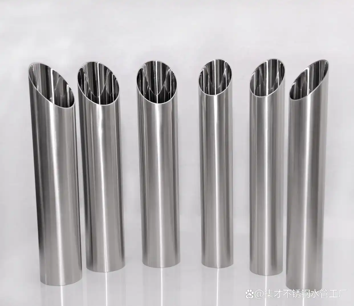
1. von DIN 11850 zwei EINS 10357
Bei der Ausführung hochreiner industrieller Prozessanlagen, Die Integration von Strukturkomponenten, die die Ansammlungswege von Mikrobakterien eliminieren, ist zwingend erforderlich. Seit Jahrzehnten, der deutsche Industriestandard DIN 11850 diente als vorherrschender technischer Rahmen in ganz Kontinentaleuropa, Festlegung der technischen Lieferbedingungen, räumliche Toleranzen, und geometrische Abmessungen für nahtlose und geschweißte Edelstahlrohre, die in der Lebensmittelindustrie verwendet werden, Molkerei, Chemische, und pharmazeutische Verarbeitungsanlagen.
Beseitigung regionaler Handelshemmnisse und Vereinheitlichung der verstreuten länderspezifischen Hygiene-Herstellungsstandards in einem gemeinsamen europäischen Regulierungsrahmen, das Europäische Komitee für Normung offiziell verabschiedet De 10357 am Anfang 2014. Mit dieser europäischen Norm wurden die technischen Voraussetzungen für hygienische Rohrleitungen in allen Mitgliedsstaaten der Europäischen Union erfolgreich harmonisiert, Etablierung einer standardisierten Basis für die Flüssigkeitshandhabungsarchitektur.
Hinweis zur strategischen Technik: Obwohl EN 10357 fungiert als formaler Rechtsnachfolger des DIN 11850, Bauliche Altsysteme und aktuelle Beschaffungsvorgaben beziehen sich häufig auf DIN-Maße. Folglich, Moderne Fertigungslinien müssen in vollständiger Übereinstimmung mit beiden Standards arbeiten, Pflege dimensionaler Unterklassen zur Anpassung an regionale technische Protokolle.
Im Rahmen einer hygienischen Layouttechnik, Es muss scharf zwischen Rohren unterschieden werden, die für allgemeine Sanitärprozesse bestimmt sind (Nahrungsmittel und Getränke) und solche, die für strenge Aseptik ausgelegt sind, sterile Anwendungen (Biotechnologie und Pharma). Während Din 11850 und EN 10357 Konzentrieren Sie sich hauptsächlich auf die Parameter der Sanitärschläuche, die passenden Beschläge, Gewerkschaften, und Komponentenmatrizen werden durch separate Standardebenen gesteuert.
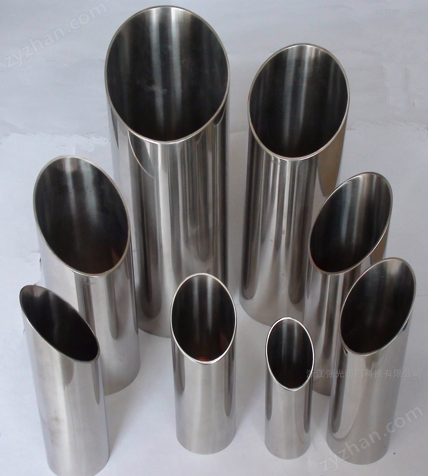
Tabelle 1: Europäische Querverweismatrix für Rohre, ARMATUREN, und aseptische Klassifizierungen
| Anwendungskategorie | Rohrabmessungen & Spezifikationen | ARMATUREN & Verbindungen | Zielbranchensegmente |
|---|---|---|---|
| Standard-Sanitär / Hygienisch | DIN 11850 (Vermächtnis) | DIN 11851 (Aufgeschmissen) DIN 11852 (SCHWEIßEN) DIN 11853 (Hygienegewerkschaften) |
Milchverarbeitung, Brauereien, Getränk, Flüssiger Lebensmitteltransport, Kosmetika |
| De 10357 (Aktuelle Norm) | |||
| Hochreine Aseptik & Steril | DIN 11866 | DIN 11864 (Aseptische Verbindungen) DIN 11865 (Aseptische Armaturen) |
Biotechnologie, Aktive pharmazeutische Inhaltsstoffe (API), Gentechnik, Halbleiterhersteller |
2. Metrische Geometrie, Strukturelle Unterklassen, und Multistandard-Harmonisierung
Zur Verwaltung der verschiedenen physischen Dimensionen, die in verschiedenen globalen Industrieökosystemen genutzt werden, De 10357 strukturiert seinen Umfang in sehr unterschiedliche dimensionale Unterklassen. Mithilfe dieser Bezeichnungen können Ingenieurteams schnell feststellen, ob eine Produktionscharge den traditionellen europäischen metrischen Standards entspricht, Amerikanische Konventionen zur hochreinen Bioverarbeitung, oder internationale Größenindizes.
- EN 10357-A (SERIE A): Entspricht den ursprünglich von der DIN vorgegebenen Legacy-Abmessungen 11850. Dies ist der primäre metrische Rahmen, der für europäische automatisierte Molkerei- und Brauereianlagen verwendet wird.
- EN 10357-C (Serie C): Kalibriert für die von der amerikanischen ASME BPE vorgeschriebenen Außendurchmesser und Wandstärken (Bioprozessausrüstung) Größenmetriken, Optimierung von Linien für die kontinentalübergreifende modulare Skid-Montage.
- EN 10357-D (Serie D): In direkter Übereinstimmung mit der internationalen ISO formuliert 2037 Abmessungen, dient als Kernstandard für Systeme, die alternative globale Komponentenlieferketten nutzen.
Eine geringfügige strukturelle Abweichung zur alten DIN 11850 Spezifikationen und der einheitlichen EN 10357 liegt in der formalen Dokumentation von Maßgrenzen für außergewöhnlich große Rohrleitungsstrecken. Speziell, De 10357 führt genaue Fertigungstoleranzgrenzen für ein $254\text{ mm}$ Rohre mit Außendurchmesser (DN 250), eine Außendimensionshülle, der ein vollständiger fehlte, explizite Strukturvorgabe im historischen deutschen Standardtext.
Tabelle 2: Dimensionsvergleich & Strukturelle Abweichungen
| Bewertungsparameter | DIN 11850 Spezifikation | De 10357 Spezifikation |
|---|---|---|
| Größenreferenzbasis | Ausschließlich metrischer Nenndurchmesser (DN) direkt an feste Millimetermaße gekoppelt. | Tri-Split-Framework, das Metric umfasst (SERIE A), ASME BPE (Serie C), und ISO 2037 (Serie D). |
| Große Durchmesser Umschlag ($254\text{ mm}$) | Nicht explizit angegeben / der individuellen Mühlenvereinbarung überlassen. | Formal standardisiert mit strukturellen Toleranzgrenzen, die unter definiert sind $\pm 0.4\text{ mm}$. |
| Nomenklatur der Oberflächenbeschaffenheit | Verwendet direkte Ausführungscodes: CC, CD, Chr, bd. | Kombiniert Strukturklassen- und Ausführungscodes: Klasse 1 (Cl1) oder Klasse 2 (CL2) + CC/CD/BC/BD. |
| Interne Druckkriterien | Formelle Tabelle mit den maximalen Bar-Zugaben bei $20^\circ\text{C}$ und $150^\circ\text{C}$. | Im offiziellen Standardtext weggelassen (lehnt sich an externe Druckbehälternormen wie EN an 13480). |
| Geradheitsbeschränkungsgrenze | Identisch in beiden Codes: $0.0015 \times \text{Length}$, mit einer maximalen Durchbiegungskappe von $2\text{ mm}$ pro laufendem Meter. |
3. Metallurgische Charakterisierung & Grenzwerte für die chemische Zusammensetzung
Die mechanische Leistung und Korrosionsbeständigkeit von Sanitärsystemen hängen stark von präzisen Stahllegierungskonfigurationen ab. Werkstoffe nach DIN 11850 und EN 10357 müssen aus hochwertigen austenitischen Edelstahlvarianten stammen, die gemäß EN synthetisiert wurden 10088-2 Kriterien. Die verwendeten Primärlegierungen sind 1.4301 (AISI 304), 1.4307 (AISI 304L), und 1.4404 (AISI 316L).
Zur Minderung interkristalliner Korrosionsrisiken innerhalb erhitzter Flüssigkeitszonen oder in der Nähe von Orbitalschweißpunkten mit hoher Temperatur, kohlenstoffarme Varianten ($C \le 0.035\%$) sind explizit angegeben 1.4307 und 1.4404 Arrays. Außerdem, der Einschluss von Molybdän ($2.0\% – 3.0\%$) innerhalb der 1.4404 Die Formulierung garantiert eine entscheidende Beständigkeit gegen lokale Lochfraß- und Spaltkorrosion beim Umgang mit sauren Prozessströmen, Reinigungslösungen, oder Medien mit hohem Salzgehalt.
Tabelle 3: Hochpräzise Grenzwerte für die chemische Zusammensetzung (ELEMENT % von Mass)
| EN-Legierungscode | AISI-Äquiv. | KOHLENSTOFF (C) | Chrom (Cr) | Nickel (Ni) | Molybdän (Mo) | Mangan (MN) | Silizium (Si) | Phosphor (P) | Schwefel (S) |
|---|---|---|---|---|---|---|---|---|---|
| 1.4301 | 304 | ≤ 0.07 | 17.5 – 19.5 | 8.0 – 10.5 | - | ≤ 2.00 | ≤ 1.00 | ≤ 0.045 | ≤ 0.015 |
| 1.4307 | 304L | ≤ 0.030 | 17.5 – 19.5 | 8.0 – 10.5 | - | ≤ 2.00 | ≤ 1.00 | ≤ 0.045 | ≤ 0.015 |
| 1.4404 | 316L | ≤ 0.030 | 16.5 – 18.5 | 10.0 – 13.0 | 2.00 – 2.50 | ≤ 2.00 | ≤ 1.00 | ≤ 0.045 | ≤ 0.015 |
4. Zugeigenschaften & Mechanische Leistungsgrenzen
Hygienerohre müssen eine robuste Balance aus hohen strukturellen Zugfestigkeiten und hervorragender Materialduktilität aufweisen. Dieses Profil ermöglicht es den Leitungen, Thermoschocks aus aufeinanderfolgenden Reinigungsprozessen sicher zu absorbieren, ohne dass es zu Rissen oder Strukturversagen kommt.
Mechanische Überprüfung, wird durch die in ASME SA270 und EN beschriebenen Testparameter geregelt 10217-7, erfordert, dass alle Strukturkomponenten einem kontrollierten thermischen Lösungsglühprotokoll unterzogen werden. Zwischendurch erhitzt $1040^\circ\text{C}$ und $1100^\circ\text{C}$ gefolgt von einem schnellen Abschrecken mit Wasser oder Luft, die Mikrostruktur wandelt sich in eine kontinuierliche um, nichtmagnetische austenitische Matrix, die vorhersagbare Dehnungswerte liefert.
Tabelle 4: Zertifizierte mechanische Eigenschaften & Bedingungen für das Lösungsglühen
| Materialspezifikation | min. Streckgrenze ($R_{p0.2}$, MPA) |
Zugfestigkeit ($R_m$, MPA) |
min. DEHNUNG ($A_5$, %) |
Lösungsglühtemperatur ($^\circ\text{C}$) |
|---|---|---|---|---|
| De 1.4301 / AISI 304 | 205 | 515 – 720 | 35% | 1040 – 1100 |
| De 1.4307 / AISI 304L | 170 | 485 – 670 | 35% | 1040 – 1100 |
| De 1.4401 / AISI 316 | 205 | 515 – 720 | 35% | 1040 – 1100 |
| De 1.4404 / AISI 316L | 170 | 485 – 670 | 35% | 1040 – 1100 |
5. Dimensionsmatrixgruppe A: Profile mit geringer Wandstärke ($1.0\text{ mm}$)
Profile mit geringer Wandstärke sind für die Flüssigkeitsverteilung bei niedrigem Druck oder Schwerkraftzuleitungen bei Umgebungstemperatur optimiert, bei denen die Reduzierung des Systemgewichts von entscheidender Bedeutung ist. Diese Konfigurationen werden häufig in Lagerbereiche mit hohem Produktvolumen integriert, Verteilungsbypassnetze, und sekundäre Entlüftungsanwendungen in automatisierten Molkereien.
Tabelle 5: Gruppe A (Lichtwand) – Nenngröße & Exakte Massenkonstanten
| Nomineller Index (DN) | Rohr-AD ($d_e$, mm) | Seit Toleranz (mm) | Wandstärke ($s$, mm) | WT-Toleranz | Endschnittzugabe | Theoretische Messe ($M$, kg/m) |
|---|---|---|---|---|---|---|
| DN 10 | 12.0 | ± 0.12 | 1.0 | ± 10% | +3.0 mm / -0.0 | 0.273 |
| DN 15 | 18.0 | ± 0.12 | 1.0 | ± 10% | +3.0 mm / -0.0 | 0.423 |
| DN 20 | 22.0 | ± 0.12 | 1.0 | ± 10% | +3.0 mm / -0.0 | 0.523 |
| DN 25 | 28.0 | ± 0.12 | 1.0 | ± 10% | +3.0 mm / -0.0 | 0.672 |
| DN 32 | 34.0 | ± 0.12 | 1.0 | ± 10% | +3.0 mm / -0.0 | 0.821 |
| DN 40 | 40.0 | ± 0.12 | 1.0 | ± 10% | +3.0 mm / -0.0 | 0.971 |
| DN 50 | 52.0 | ± 0.20 | 1.0 | ± 10% | +3.0 mm / -0.0 | 1.271 |
6. Dimensionsmatrixgruppe B: Standard-Wandstärkenprofile ($1.5\text{ mm} – 2.0\text{ mm}$)
Die Zwischenprofilkonfiguration der Gruppe B vereint hohe strukturelle Festigkeit mit leichter Effizienz. Dieser Querschnitt behandelt Standardkommunen, Pharmazeutisch, und Betriebsdrücke von Chemieanlagen, Damit ist es das primäre Dimensionsformat für Wasseraufbereitungssysteme, Produkttransportlinien, und allgemeine Architektur der Rohproduktaufnahme.
Tabelle 6: Gruppe B (Standardwand) – Vollständige metrische Größen- und Massenindizes
| Nomineller Index (DN) | Rohr-AD ($d_e$, mm) | Seit Toleranz (mm) | Wandstärke ($s$, mm) | WT-Toleranz | Linearer Längenbereich (M) | Theoretische Messe ($M$, kg/m) |
|---|---|---|---|---|---|---|
| DN 10 | 13.0 | ± 0.30 | 1.5 | ± 10% | 6.00 | 0.431 |
| DN 15 | 19.0 | ± 0.30 | 1.5 | ± 10% | 6.00 | 0.655 |
| DN 20 | 23.0 | ± 0.30 | 1.5 | ± 10% | 6.00 | 0.805 |
| DN 25 | 29.0 | ± 0.30 | 1.5 | ± 10% | 6.00 | 1.030 |
| DN 32 | 35.0 | ± 0.30 | 1.5 | ± 10% | 6.00 | 1.255 |
| DN 40 | 41.0 | ± 0.30 | 1.5 | ± 10% | 6.00 | 1.480 |
| DN 50 | 53.0 | ± 0.30 | 1.5 | ± 10% | 6.00 | 1.931 |
| DN 65 | 70.0 | ± 0.30 | 2.0 | ± 10% | 6.00 | 3.400 |
| DN 80 | 85.0 | ± 0.30 | 2.0 | ± 10% | 6.00 | 4.150 |
| DN 100 | 104.0 | ± 0.30 | 2.0 | ± 10% | 6.00 | 5.101 |
| DN 125 | 129.0 | ± 0.40 | 2.0 | ± 10% | 6.00 | 6.350 |
| DN 150 | 154.0 | ± 0.40 | 2.0 | ± 10% | 6.00 | 7.601 |
| DN 200 | 204.0 | ± 0.40 | 2.0 | ± 10% | 6.00 | 10.100 |
| DN 250 | 254.0 | ± 0.40 | 2.0 | ± 10% | 6.00 | 12.601 |
7. Dimensionsmatrixgruppe C: Profile mit hoher Wandstärke ($2.0\text{ mm} – 2.5\text{ mm}$)
Für Hochtemperatur-Verarbeitungszonen, sterile Dampfschleifen, oder Leitungen, die stark korrosive chemische Verbindungen transportieren, Sich auf leichte Strukturen zu verlassen, birgt betriebliche Risiken. Dickwandige Konfigurationen der Gruppe C bieten den für mehrstufige Pasteurisierungsanordnungen erforderlichen Berstdruck-Sicherheitsfaktor, Hochgeschwindigkeitsverdampfungslinien, und moderne chemische Verarbeitungsanlagen.
Tabelle 7: Gruppe C (Schwere Mauer) – Geometrische Parameter & Massenwerte
| Nomineller Index (DN) | Rohr-AD ($d_e$, mm) | Seit Toleranz (mm) | Wandstärke ($s$, mm) | WT-Toleranz | Rechtwinkligkeitsbeschränkung beenden | Theoretische Messe ($M$, kg/m) |
|---|---|---|---|---|---|---|
| DN 10 | 14.0 | ± 0.30 | 2.0 | ± 10% | ≤ 0.5% von OD | 0.601 |
| DN 15 | 20.0 | ± 0.30 | 2.0 | ± 10% | ≤ 0.5% von OD | 0.901 |
| DN 20 | 24.0 | ± 0.30 | 2.0 | ± 10% | ≤ 0.5% von OD | 1.102 |
| DN 25 | 30.0 | ± 0.30 | 2.0 | ± 10% | ≤ 0.5% von OD | 1.402 |
| DN 32 | 36.0 | ± 0.30 | 2.0 | ± 10% | ≤ 0.5% von OD | 1.703 |
| DN 40 | 42.0 | ± 0.30 | 2.0 | ± 10% | ≤ 0.5% von OD | 2.003 |
| DN 50 | 54.0 | ± 0.30 | 2.0 | ± 10% | ≤ 0.5% von OD | 2.604 |
8. Hydrostatische Innendruckschwellen & Strukturberechnungen
Im Gegensatz zu alten deutschen Regeln, De 10357 definiert in seinem Haupttext nicht explizit interne Druckgrenzen, Stattdessen wird auf die regionalen Konstruktionsvorschriften für Druckbehälter zurückgegriffen. allerdings, um bauliche Sicherheitsfaktoren zu gewährleisten, Ingenieurteams verlassen sich auf die in der DIN erfassten Kernformeln 11850 and AD-Merkblatt B1/B9.
Die grundlegenden Berechnungen der strukturellen Kapazität bewerten ein zylindrisches Schalensegment ohne Ausschnitte ($P_{max}$), vorausgesetzt a 100% effiziente Längsschweißverbindung. Denn austenitischer Stahl wird bei höheren Temperaturen weicher, Die Druckstufen müssen um bis zu reduziert werden 40% beim Betrieb unter Sterilization-in-Place (SCHLUCK) Bedingungen bei $150^\circ\text{C}$.
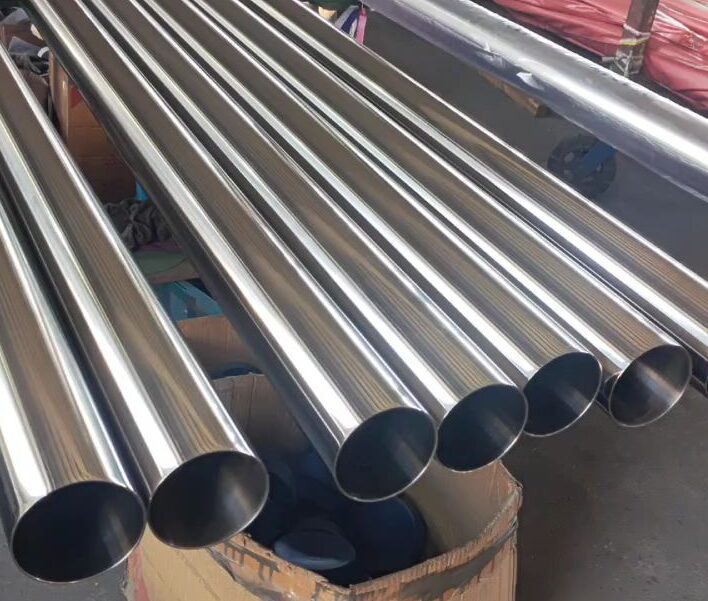
Tabelle 8: Maximale Betriebsdruckgrenzen (Bar) für 1.4301 Geschweißte Konfigurationen
| DN-Größencode | 10 | 15 | 20 | 25 | 32 | 40 | 50 | 65 | 80 | 100 | 125 | 150 | 200 |
|---|---|---|---|---|---|---|---|---|---|---|---|---|---|
| Limit bei $20^\circ\text{C}$ (Bar) | 355 | 242 | 200 | 159 | 131 | 112 | 87 | 87 | 72 | 59 | 47 | 39 | 30 |
| Limit bei $150^\circ\text{C}$ (Bar) | 219 | 150 | 124 | 98 | 81 | 69 | 53 | 54 | 44 | 36 | 29 | 24 | 18 |
9. Topographie der inneren Oberflächenbeschaffenheit & Mikrorauheitskonstanten
Eine strikte Kontrolle der inneren Oberflächentopographie ist wichtig, um das Wachstum von Mikroben oder die Anhaftung von Biofilmen zu verhindern. Beide Standards erzwingen strenge Beschränkungen für den maximal zulässigen internen Rauheitsdurchschnitt ($R_a$).
Um eine wiederholbare Reinigungsfähigkeit während des Clean-in-Place sicherzustellen (CIP) Prozesse, Die Innenfläche muss eine bleiben $R_a \le 0.8\ \mu\text{m}$. Für hochreine Pharmabereiche, Die Endbearbeitungsanforderungen werden weiter eingeschränkt $R_a \le 0.4\ \mu\text{m}$ oder besser, Typischerweise wird dies durch spezielles mechanisches Schleifen und anschließendes Elektropolieren erreicht.
Tabelle 9: Bezeichnungen für die Oberflächenrauheit, Behandlungsprotokolle & Zielgrenzen
| EN-Code | Legacy-Code | Prozessstatus & Thermische Behandlung | Innerer Körper ($R_a\ \mu\text{m}$) | Schweißnaht ($R_a\ \mu\text{m}$) | Außenfläche ($R_a\ \mu\text{m}$) |
|---|---|---|---|---|---|
| CL1 BC | Chr | Blankgeglüht, Mechanisch poliert | ≤ 0.80 | ≤ 1.60 | eingelegt (≤ 1.60) |
| CL1 BD | bd | Blankgeglüht, Boden draußen | ≤ 0.80 | ≤ 1.60 | ≤ 1.00 |
| CL1 CC | CC | Nicht geglüht, Sauber eingelegt | ≤ 0.80 | ≤ 1.60 | eingelegt (≤ 1.60) |
| CL1-CD | CD | Nicht geglüht, Äußerlich geerdet | ≤ 0.80 | ≤ 1.60 | ≤ 1.00 |
| Tri-Clover | 3Eine Spezifikation | Hochreine elektropolierte Variante | ≤ 0.38 | ≤ 0.38 | ≤ 0.80 |
10. Alternative Oberflächentopographie & Konvertierung der Körnung zum Polieren
Unterstützung der Beschaffungsabteilungen bei der Bewertung internationaler Lieferungen, Die Umrechnung mechanischer Körnungsbezeichnungen in präzise messtechnische Werte ist unerlässlich. Während sich die Körnung auf die Partikeldichte des Schleifmediums bezieht, Die formalen Zertifizierungskriterien basieren auf tatsächlichen Rauheitsmessungen ($R_a$) um die Einhaltung der Hygienevorschriften zu überprüfen.
Tabelle 10: Verarbeitung von Schleifkörnern bis zur Rauheit Mikron / Mikrozoll-Umrechnung
| Format für die Schleifbearbeitung | Rauheit ($R_a$, Mikrozoll) | Rauheit ($R_a$, Mikrometer) | ISO 4287 Bezeichnung | Nachschicht mit elektropolierendem Polierfinish |
|---|---|---|---|---|
| 150 Körniges Finish | 30 – 35 | 0.75 – 0.875 | N6 | Nicht anwendbar |
| 150 Streugut + Elektropolieren | 12 – 20 | 0.30 – 0.50 | N5 | Vollständig angewendet |
| 180 Körniges Finish | 20 – 25 | 0.50 – 0.625 | N5 | Nicht anwendbar |
| 180 Streugut + Elektropolieren | 10 – 16 | 0.25 – 0.40 | N4 | Vollständig angewendet |
| 240 Körniges Finish | 15 – 20 | 0.375 – 0.50 | N5 | Nicht anwendbar |
| 240 Streugut + Elektropolieren | 8 – 12 | 0.20 – 0.30 | N4 | Vollständig angewendet |
| 320 Körniges Finish | 8 – 12 | 0.20 – 0.30 | N4 | Nicht anwendbar |
| 320 Streugut + Elektropolieren | 6 – 12 | 0.15 – 0.30 | Ultra-sauber | Vollständig angewendet |
11. Qualitätskontrollprotokolle, Testmethoden & Metrologiestandards
Überprüfung der Einhaltung der EN 10357 und von 11850 erfordert strenge zerstörungsfreie und zerstörende Tests. mechanische Eigenschaften, chemische Matrizen, und Oberflächenparameter müssen gemäß validiert werden De 10217-7 Testkategorie 1 (TC1) Regeln, oder Testkategorie 2 (TC2) protocols under AD-2000-Merkblatt W2 conditions.
Anschließend werden Rauheitsprüfungen durchgeführt IHRE EN ISO 4287 und IHRE EN ISO 4288 Protokolle. Prüfer messen Oberflächenparameter am Rohrende, genau $5\text{ mm}$ vom Rand, mindestens auswerten 1 in 20 Rohre aus jeder Produktionswärme. Für außengeschliffene Profile (Typen CD und BD), Es werden mindestens Verhältnismessungen durchgeführt $100\text{ mm}$ vom Rohrende, um Kantenverzerrungen auszuschließen.
Tabelle 11: Schwellenwertmatrix für vorgeschriebene QA-Inspektionstests
| Ziel testen | Referenznorm | Verfahrensmethode / Kriterien | Mindestfrequenz |
|---|---|---|---|
| Integrität der Schweißnaht | De 10217-7 / IN ISO 10893-1 | Kontinuierliche zerstörungsfreie Wirbelstromprüfung oder hydrostatische Prüfschleifen. | 100% der Charge |
| Oberflächenrauheit ($R_a$) | IHRE EN ISO 4287 / 4288 | Messung des Stiftprofilometers $5\text{ mm}$ vom Rohrende über die Schweißzone und das innere Grundmetall. | 5% von Längen (1:20) |
| Dimensionskonformität | De 10357 / DIN 11850 | Bestätigung des Außendurchmessers im Mikrometerbereich und Wandscans der Wandstärke per Laser. | 100% der Charge |
| Schweißverformbarkeit | IN ISO 8492 / 8493 | Zerstörende Ringabflachungs- und Driftdehnungstests zur Bestätigung der Kaltumformflexibilität. | Einmal pro Wärmebündel |
12. Systemrückverfolgbarkeit, Markierungsstandards & Mühlenzertifizierungen
Die lückenlose Materialrückverfolgbarkeit ist eine Grundlage moderner Sanitärtechnik Qualität Sicherheit. In hochreinen Verarbeitungsbereichen, Eine vollständige Bestandsverfolgung stellt sicher, dass etwaige Rohmaterialdefekte schnell isoliert werden können, Risikominimierung in der gesamten Produktionskette.
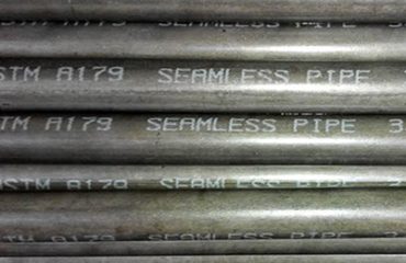
Zur Aufrechterhaltung der Dokumentationsintegrität, Alle Rohre müssen deutlich mit dem Herstellerzeichen versehen sein, Standardcodes, Abmessungen, Oberflächenspezifikation, und die spezifische Materialwärmezahl. Außerdem, Lieferungen müssen ein zertifiziertes Zertifikat enthalten De 10204 3.1 Materialtestbericht (mtr), Validierung der genauen chemischen Zusammensetzung und der mechanischen Eigenschaften.
Tabelle 12: Vorgeschriebene Stempel- und Dokumentationsprüfung
| Erforderlicher Markierungsparameter | Beispiel für eine Stempelsyntax | Verifizierungsanforderung |
|---|---|---|
| Herkunftsverfolgung | MÜHLENNAME DEUTSCHLAND | Identifiziert den Produktionsstandort und -standort. |
| Standardkonformität | EN 10357-A / DIN 11850 | Bestätigt das dimensionale Unterklassen-Framework. |
| Dimensionsprofil | DN50 $53.0 \times 1.5\text{ mm}$ | Bestätigt Außendurchmesser und Wandstärke. |
| Oberflächenausführungscode | CL1 BD | Validiert die Rauheitsklassenkriterien. |
| Rückverfolgbarkeitsidentität | HEIZ NR. H2026X57 | Verlinkt zurück zum Chargenprofil der Schmelzerei. |
13. Kompatibilität mit Elastomerdichtungen & Chemikalienbeständigkeitsprofile
Der Aufbau eines zuverlässigen, hygienischen Prozesssystems erfordert die Auswahl kompatibler Elastomerdichtungen zum Abdichten von Verbindungskupplungen, Überwurfmuttern, und Tri-Clamp-Aderendhülsen. Ungeeignete Elastomermischungen können sich schnell zersetzen, wenn sie aggressiven Produktchemikalien oder rauem Clean-in-Place ausgesetzt werden (CIP) Lösungen.
zum Beispiel, Standard-Nitrilkautschuk (NBR) zeigt eine begrenzte Widerstandsfähigkeit, wenn es hochkonzentrierten Heißlaugezyklen oder aktiven Dampfleitungen ausgesetzt wird. Umgekehrt, Premium-Polymere wie Ethylen-Propylen-Dien-Monomer (EPDM) oder Polytetrafluorethylen (PTFE) Bewahren Sie die Materialintegrität unter intensiven Sterilisationsumgebungen, Verhindert eine Verschlechterung der Dichtung und eine Kontamination der Prozessflüssigkeit.
Tabelle 13: Umfassende Produkt- und Chemikalienbeständigkeitsbewertungen für Elastomerverbindungen
| Medientyp oder Prozessstrom | NBR | HNBR | EPDM | Silikon (Q) | FPM (Viton) | PTFE (Teflon) |
|---|---|---|---|---|---|---|
| Standard-Molkerei (Milch, Creme) | 3 | 3-4 | 3-4 | 3-4 | - | 4 (hoch) |
| Sorten kultivierter Sauermilch | 3 | 3-4 | 3-4 | 3-4 | - | 4 (hoch) |
| Brauereiströme (Bier, Hopfen) | 3 | 3-4 | 3-4 | 1-2 | 2-3 | 4 (hoch) |
| Weinverarbeitung und Hefen | 3 | 3-4 | 4 | 4 | 2-3 | 4 (hoch) |
| Tier & Pflanzliche Fette (An $100^\circ\text{C}$) | 3 | 4 | 1-2 | 3 | 4 | 4 (hoch) |
| Heißes Prozesswasser / Dampf (An $130^\circ\text{C}$) | 1 (Scheitern) | 4 | 4 | 2 | - | 4 (hoch) |
| Nicht oxidierende Säuren (An $80^\circ\text{C}$) | 1-2 | 2 | 3 | 1-2 | 2 | 3-4 |
| Schwach alkalische Laugenmischungen (An $100^\circ\text{C}$) | 2 | 3-4 | 4 | 2 | 2 | 4 (hoch) |
| Konzentrierte CIP-Laugenreiniger | 1 (Scheitern) | 2-3 | 3 | 1 | 1 | 4 (hoch) |
* Hinweis: Leistungsindizierungswerte werden gemäß der globalen ISO R zusammengestellt 1629 Regeln zur Gummiklassifizierung. (Schlüssel: 4 = Hohe Eignung; 3 = Normale Eignung; 2 = Begrenzte Eignung; 1 = Ungeeignet).
14. Innerer geometrischer Bereich & Volumetrische Verschiebungsmatrizen
Die Berechnung der genauen Flüssigkeitsverdrängung erfordert die Analyse des genauen Innendurchmessers ($d_i$) des Rohrverlaufs. Weil die Wanddickenparameter in den verschiedenen Strukturserien variieren, Die innere Querschnittsfläche ändert sich erheblich zwischen den Klassen der Gruppen A und C.
Hygienisches Prozessdesign erfordert die Minimierung des Strömungswiderstands und die Aufrechterhaltung optimaler Druckbedingungen. In der folgenden Tabelle sind die tatsächlichen Innenquerschnittsflächen und relativen Flüssigkeitskapazitäten für die wichtigsten Segmente mit Standard-Nenndurchmesser aufgeführt.
Tabelle 14: Wahre interne Querschnittsflächen- und Kapazitätsindexmatrix
| Größenindex (DN) | Standard-Außendurchmesser (mm) | Wandklasse (mm) | Wahre ID ($d_i$, mm) | Interner Bereich ($\text{cm}^2$) | Einheit Flüssigkeitsvolumen. (L/m) |
|---|---|---|---|---|---|
| DN 25 | 29.0 | 1.5 | 26.0 | 5.31 | 0.531 |
| 2.0 | 25.0 | 4.91 | 0.491 | ||
| DN 50 | 53.0 | 1.5 | 50.0 | 19.63 | 1.963 |
| 2.0 | 49.0 | 18.86 | 1.886 | ||
| DN 100 | 104.0 | 2.0 | 100.0 | 78.54 | 7.854 |
| 2.5 | 99.0 | 76.97 | 7.697 |
15. Schweißspezifikationen & Wärme-betroffene Zone (HAZ) Sicherheit
Um hygienische Leitungen zu verbinden und gleichzeitig den Flussweg glatt und nahtlos zu halten, Automatisiertes orbitales WIG-Schweißen ist weit verbreitet. Einen Höhepunkt erreichen-Qualität Bei der Verbindung muss der Wärmeeintrag kontrolliert werden, um die Ausfällung von Chromkarbid entlang der Korngrenzen zu verhindern.
Ein ordnungsgemäßes Sauerstoffmanagement im Rohr während des Schweißens ist von entscheidender Bedeutung. Verwendung von hochreinem Argon-Schutzgas ($>99.995\%$) sorgt für einen niedrigen Sauerstoffgehalt in der Spülkammer, Eliminierung von Oxidverfärbungen, die die passive Oberflächenschicht beeinträchtigen und zu Korrosion führen können.
Tabelle 15: Orbitale WIG-Schweißparameter & Abschirmungsprotokolle löschen
| Schweißparameter | Operatives Ziel & Kontrollierte Einstellungen | Zielwertmetrik |
|---|---|---|
| Sauerstoffgrenzwert spülen | Maximal zulässige Sauerstoffkonzentration im internen Spülpfad vor Beginn der Lichtbogensequenz. Verhindert die Oxidation der Schweißwurzel. | ≤ 25 ppm |
| Reinheit des Schutzgases | Zusammensetzung des Brenners und des Hintergrundgases. Muss völlig frei von Kohlenwasserstoffen und Feuchtigkeit sein, um Schweißporosität zu vermeiden. | 99.995% Argon min. |
| Linearer Wärmeeintrag | Beim Schweißen pro Längeneinheit abgegebene Energie. Kontrolliert, um das mikrostrukturelle Gleichgewicht aufrechtzuerhalten und das Kornwachstum zu verhindern. | 0.5 – 1.2 KJ/mm |
| Fehlausrichtungsgrenze | Maximal zulässige Stufenhöhe zwischen passenden Rohrwänden an der Verbindungsstelle. Verhindert innere Spalten, in denen sich Prozessflüssigkeit ansammeln kann. | ≤ 10% der Wandstärke |
16. Logistik vor Ort, Speicherprotokolle & Kriterien für die Installationsausrichtung
Um die Präzisionstoleranzen und die Oberflächenqualität von Hygienerohren zu wahren, ist eine sorgfältige Materialhandhabung beim Versand und bei der Lagerung vor Ort erforderlich. Um galvanische Kontamination zu vermeiden, Edelstahlprofile müssen getrennt von Kohlenstoffstahlkomponenten gelagert werden.
Rohre sollten durch Holzpolsterstreifen oder gepolsterte Gestelle gestützt werden, um eine Verformung durch Punktlast zu verhindern. Zusätzlich, Hochreine Leitungen müssen mit einem gleichmäßigen Gefälle verlegt werden, um eine vollständige Selbstentleerung zu gewährleisten, Eliminierung von Flüssigkeitseinschlusszonen, die die Systemhygiene beeinträchtigen könnten.
Tabelle 16: Anforderungen an Lagerung und Handhabung vor Ort
| Handhabungsphase | Vorgeschriebenes Verfahren & Schutzkriterien | Zielgrenzmetrik |
|---|---|---|
| Lagerlagerung | Auf gepolsterten Gestellen drinnen lagern, isoliert aus Kohlenstoffstahl. Halten Sie die schützenden Endkappen aus Kunststoff fest an Ort und Stelle, um Staub in der Luft zu vermeiden. | 100% trockene Umgebung |
| Hebelogistik | Verwenden Sie beim Transport saubere Nylonschlingen oder polymerbeschichtete Haken. Niemals blanke Stahlketten oder Gabelstapler direkt an Edelstahlrohrbündeln verwenden. | Keine Oberflächenkerbe |
| Entwässerungsausrichtung | Horizontale Leitungen müssen in Richtung der Ablassventile nach unten geneigt sein, um eine vollständige Evakuierung des Systems während der Reinigungszyklen sicherzustellen. | min. Neigung 1:100 (1%) |
17. Zerstörungsfreie Prüfung (NDT) & Überprüfung der metallurgischen Integrität
Sicherstellung der Einhaltung der strengen Standards für europäische Lebensmittel, Molkerei, und pharmazeutische Produktionsmatrix, jeder Produktionslauf von EN 10357 / DIN 11850 Rohre müssen eine strenge Matrix interner zerstörungsfreier Tests bestehen. Diese Verfahren gewährleisten eine strukturelle Beständigkeit unter zyklischer thermischer Belastung und eliminieren das Risiko von Lochleckagen bei hohen Prozessdrücken.
Die primäre inline eingesetzte Methode ist 100% automatisierte Wirbelstromprüfung in voller Übereinstimmung mit EN ISO 10893-1 oder EN ISO 10893-2. Dieses elektromagnetische Prüfsystem bewertet schnell die Kontinuität sowohl der Grundmetallmatrix als auch der autogenen Schweißnaht, Isolierung mikroskopischer Längsrisse in der Wand, Schlackeneinschlüsse, oder innere Gastaschen, die mit bloßem Auge nicht sichtbar sind.
Tabelle 17: Obligatorische Qualitätsinspektionsmatrix und Akzeptanz-Benchmarks
| Testkategorie | Testmethodik & Referenzverordnung | Vorgeschriebener Akzeptanzstandard |
|---|---|---|
| Wirbelstrom-Fehlererkennung | Kontinuierliche elektromagnetische Inline-Bewertung mit dem Ziel der Integrität der Hauptstreifen- und Nahtschweißzone gemäß EN ISO 10893-2. | Nullsignalabweichung (Keine Risse) |
| Mechanische Schweißnahtabflachung | Zerstörende Bewertung durch starke Druckverformung von Probenstücken bei 90°-Ausrichtung relativ zur Schweißebene gemäß EN ISO 8492. | Keine Mikrorisse oder Schweißrisse |
| Dimensionales Laser-Audit | Kontinuierliche berührungslose Hochgeschwindigkeits-360-Grad-Lasertelemetrie zur Bestätigung der Gleichmäßigkeit des nominalen Außendurchmessers und der Rundheit des Querschnitts. | Streng innerhalb EN 10357 Umschlag |
18. Chemische Passivierung nach der Herstellung & Optimierung der Oberflächenchemie
Um ein maximales lokales Lochfraß-Widerstandsäquivalent zu erreichen (HOLZ) Metriken innerhalb von Prozessnetzwerken, fertige austenitische und Duplex-Hygienestahlrohre werden einer präzisen chemischen Tauchpassivierung unterzogen. Durch diese metallurgische Verarbeitung wird jegliches spurenelementfreie Eisen, das an der Innenwand des Rohrs eingebettet ist, aus rohen mechanischen Zieh- und Poliermedien entfernt.
Durch den Kontakt der ultraglatten Oberflächen mit gezielten Salpetersäureformulierungen ($HNO_3$) oder organische Zitronensäure, Die Chromkonzentration an der Oberfläche steigt im Vergleich zu Eisen künstlich an. Dieser Prozess beschleunigt die Erzeugung einer kontinuierlichen, kohäsives Chromoxid ($Cr_2O_3$) passive Barriereschicht. Diese molekulare Barriere blockiert effektiv das Eindringen von Ionen durch aggressive CIP-Reinigungsmedien, die heiße Natronlauge oder saure Desinfektionsmittel enthalten.
Tabelle 18: Standardparameter für die industrielle chemische Passivierung
| Chemische Formulierung | Volumetrische Lösungstemp. | Eintauchdauer | Ziel-Pass-Passiv-Verhältnis |
|---|---|---|---|
| Salpetersäure (20% – 25% $HNO_3$) | 45° C – 55° C | 20 – 30 Minuten | Cr:Fe-Verhältnis ≥ 1.5 über XPS |
| Zitronensäure (4% – 10% Chelatbildung) | 50° C – 65° C | 30 – 45 Minuten | Cr:Fe-Verhältnis ≥ 1.2 über XPS |
19. Regulatorische Rückverfolgbarkeit & Materialzertifizierungsstandards
In sterilen Verarbeitungsumgebungen, Materielle Herkunft und strukturelle Transparenz sind nicht verhandelbare rechtliche Gebote. Alle Rohrleitungsmaterialien nach EN gebaut 10357 muss eine ununterbrochene Strukturverfolgung von der ersten Schmelzphase bis hin zu den letzten Endbearbeitungsvorgängen aufrechterhalten. Jede Charge ist über eine unauslöschliche Lasermarkierung entlang der Außenlänge des Rohrprofils mit einer spezifischen Mühlenwärmenummer verknüpft.
Um die strukturelle Freigabe durch Systemprüfer sicherzustellen, Die Lieferpapiere müssen eine offizielle EN enthalten 10204 Geben 3.1 Prüfbescheinigung. Dieses Dokument verfolgt die chemischen Konfigurationen von Pfannenproben, genaue mechanische Ausfallmetriken (einschließlich Streckgrenzen $R_{p0.2}$, ultimative Zuggrenzen $R_m$, und prozentuale Dehnung $A$), sowie dokumentierte Mikrometerrauheit der Innenwand ($R_a$) Parameter.
Tabelle 19: Regulatorische Rahmenstandards für die Rückverfolgbarkeit
| Regulierungsmechanismus | Überprüfungsumfang & Tracking-Attribute | Konformitätsstufe |
|---|---|---|
| De 10204 Geben 3.1 Zertifikat | Obligatorische Validierung, die reale physikalische mechanische Ergebnisse der Mühle und chemische Werte von unabhängigen Prüfaufsichtsbehörden auflistet. | Vollständig rückverfolgbare Wärmeverfolgung |
| EG-Nr 1935/2004 Ausrichtung | Bestätigt, dass die Legierungsformulierung bei Betriebskontakt keine gefährlichen schweren Elemente in flüssige Lebensmittelströme auslaugen wird. | Für den Lebensmittelkontakt zugelassen |
| Kontinuierliches Laser-Schablonieren | Permanente Markierung der Strukturoberfläche unter Angabe der Standard-Referenzcodes, genaue Abmessungen, Name der Stahlsorte, und primärer Wärmecode. | 100% Identifizierung vor Ort |
20. CIP/SIP-Protokollkompatibilität & Chemikalien zur vorbeugenden Wartung
Beibehaltung der extrem niedrigen inneren Oberflächenrauheit ($R_a \le 0.40\,\mu\text{m} – 0.80\,\mu\text{m}$) von EN 10357 Hygiene von Rohrleitungen über mehrjährige Produktionskampagnen erfordert die strikte Einhaltung standardisierter Clean-In-Place (CIP) und Steam-In-Place (SCHLUCK) thermische Regime. Unsachgemäßer Kontakt mit Chemikalien oder unzureichende Flüssigkeitsgeschwindigkeiten können zu örtlich begrenzten Schäden führen “Rouge”– die Bildung mikroskaliger Eisenoxid- oder Hydroxidfilme, die die passive Chromoxidschicht abbauen.
Zur gründlichen Entfernung organischer Rückstände und zur Neutralisierung biologischer Matrizen, ohne Lochfraß zu verursachen, Verarbeitungslinien müssen einem abwechselnden Zyklus aus formulierten alkalischen Reinigungsmitteln und sauren Neutralisierungsspülungen ausgesetzt sein. Außerdem, SIP-Vorgänge mit Sattdampf bis zu 134 °C erfordern eine sorgfältige Überwachung der Wärmeausdehnungsvariablen ($16.5 \times 10^{-6}/\text{K}$ für 1.4404 Stehlen) um mechanische Spannungen entlang der inneren Orbitalschweißnähte zu beseitigen.
Tabelle 20: Standardschwellenwerte für CIP/SIP-Betriebszyklen
| Betriebsphase | Chemische Zusammensetzung / Medium | Wärmebereich | Kinetische Zielschwelle |
|---|---|---|---|
| Alkalische CIP-Wäsche | Natriumhydroxid ($NaOH$) 1.0% – 2.0% WT. | 75° C – 85° C | min. Geschwindigkeit: 1.5 MS |
| Saure CIP-Spülung | Salpetersäure ($HNO_3$) 0.5% – 1.0% WT. | 50° C – 60° C | Passivierungswartung |
| SIP-Wärmezyklus | Gesättigter, sauberer Dampf (Trockenheit > 95%) | 121° C – 134° C | Belichtung: 20 – 30 Min |
21. Flüssigkeitsdynamik & Mechanische Überlegungen zur Grenzschicht
Aus ingenieurwissenschaftlicher Sicht, die von EN definierten Innenmaßmatrizen 10357 (Serien A bis D) werden mathematisch optimiert, um turbulente Strömungsprofile und Grenzschicht-Scherspannungen zu kontrollieren. Wenn hochviskose Lebensmittelmischungen oder scherempfindliche biologische Materialien ein Hygienenetzwerk durchlaufen, Das glatte Wanddesign minimiert Druckverluste und verhindert eine innere Taschentrennung.
Aufrechterhaltung eines voll entwickelten turbulenten Strömungsregimes (Reynolds Nummer $Re > 4000$) Während der CIP-Durchführung ist es wichtig, die erforderliche Wandschubspannung zu erzeugen, um den Biofilm mechanisch zu entfernen. Denn die Querschnittsgeometrie der Serie A passt exakt zu metrischen Pumpen und Armaturen, Prozessanlagen können den Einsatz von konzentrischen Reduzierstücken minimieren, Reduzierung turbulenzbedingter Kavitationsflecken, die darunter liegende passive Chromoberflächen erodieren.
Tabelle 21: Hydraulische Bewertungsparameter für Nenngrößen (SERIE A)
| Normale Größe | Innendurchmesser ($D_i$) | Querschnitt des Strömungsbereichs | Zielvolumenrate (bei 1.5 MS) |
|---|---|---|---|
| DN25 | 26.0 mm | 530.9 $\text{mm}^2$ | ~ 2.87 $\text{m}^3/\text{h}$ |
| DN40 | 38.0 mm | 1134.1 $\text{mm}^2$ | ~ 6.12 $\text{m}^3/\text{h}$ |
| DN50 | 50.0 mm | 1963.5 $\text{mm}^2$ | ~ 10.60 $\text{m}^3/\text{h}$ |
| DN100 | 100.0 mm | 7854.0 $\text{mm}^2$ | ~ 42.41 $\text{m}^3/\text{h}$ |
Die chemischen Zusammensetzungen, Strukturparameter, und Maßkonfigurationen in diesem Verzeichnis entsprechen den offiziellen europäischen Normen. Vor der Fertigstellung von Prozesslayouts oder technischen Berechnungen für Rohrleitungssysteme, Überprüfen Sie die einzelnen Anforderungen anhand der vom Werk herausgegebenen EN 10204 3.1 Prüfbescheinigung.
Sie müssen eingeloggt sein, um ein Kommentar abzugeben.